background image

48

 LCD Module Disassembly Process

LCD Module Disassembly Flowchart

Screw List

Remove

Inverter Board

Remove

LCD Panel

Remove

LCD Bezel

Remove

LCD FPC Cable

Remove

Camera Module

Remove LCD

Panel from Main

Unit before
proceeding

Remove

LCD Brackets

Remove

Antennas

Remove

MIC Cable

Summary of Contents for TravelMate 6493 Series

Page 1: ...TravelMate 6493 Series Disassembly Instruction PRINTED IN TAIWAN please refer to http csd acer com tw ...

Page 2: ...e the computer you need the following tools Wrist grounding strap and conductive mat for preventing electrostatic discharge Flat screwdriver Philips screwdriver Plastic flat screwdriver Plastic tweezers NOTE The screws for the different components vary in size During the disassembly process group the screws with the corresponding components to avoid mismatch when putting back the components Chapte...

Page 3: ...the battery pack Disassembly Process The disassembly process is divided into the following stages External module disassembly Main unit disassembly LCD module disassembly The flowcharts provided in the succeeding disassembly sections illustrate the entire disassembly sequence Observe the order of the sequence to avoid damage to any of the hardware components For example if you want to remove the m...

Page 4: ... components that need to be removed during servicing For example if you want to remove the main board you must first remove the keyboard then disassemble the inside assembly frame in that order Screw List Disconnect power and signal cables from system Remove Battery Turn off system and peripherals power Remove DIMMs Remove 3G Card Remove HDD Remove ODD Remove Lower Covers Remove Dummy Cards ...

Page 5: ...o the unlock position 3 Slide and hold the battery release latch to the release position 1 then slide out the battery pack from the main unit 2 1 2 NOTE Battery has been highlighted with the red circle as above image shows Please detach the battery and follow local regulations for disposal ...

Page 6: ...5 Removing the SD dummy card 1 Push the SD dummy card in to eject it 2 Grasp the card and pull it out from the slot ...

Page 7: ...6 Removing the NewCard Dummy card 1 Push the NewCard eject button to eject it then push it all the way in to eject the NewCard dummy 2 Pull it out from the slot ...

Page 8: ...ttery Pack 2 See Removing the SD dummy card 3 See Removing the NewCard Dummy card 4 Loosen the five captive screws in the Memory HDD and 3G bays as shown 5 Carefully open the memory cover 6 Remove the HDD cover as shown HDD Cover Memory Cover 3G Cover ...

Page 9: ...8 7 Remove the 3G cover as shown ...

Page 10: ...ing the Battery Pack 2 Remove the Memory Module cover See Removing the Lower Covers 3 Push out the release latches on both sides of the DIMM socket to release the DIMM module 4 Remove the DIMM module 5 Repeat steps for the second DIMM module ...

Page 11: ...e Battery Pack 2 Remove the 3G cover See Removing the Lower Covers 3 Disconnect the antenna cables from the 3G board 4 Move the antenna cables away and remove the two screws to release the 3G board Step Size Quantity Screw Type 3G Module M2 3 2 ...

Page 12: ...ive Module 1 See Removing the Battery Pack 2 Remove the HDD cover See Removing the Lower Covers 3 Use the mylar tab to slide and lift up the hard disk drive module to remove NOTE To prevent damage to device avoid pressing down on it or placing heavy objects on top of it ...

Page 13: ...e the HDD holder by easing the sides outward to clear the carrier 5 Remove the four screws securing the hard disk to the carrier 6 Remove the HDD from the carrier Step Size Quantity Screw Type HDD Carrier M3 3 4 ...

Page 14: ...rive Module 1 See Removing the Battery Pack 2 Remove the Memory cover See Removing the Lower Covers 3 Push the ODD release latch to eject the ODD module 4 Pull the ODD module through the chassis to remove it from the main unit ...

Page 15: ...it from the ODD module 6 Remove the ODD board from the ODD module by disconnecting the interface as shown 7 Insert a pin in the eject hole of the ODD to eject the ODD tray Step Size Quantity Screw Type ODD Bracket red callout M2 5 2 ODD Bracket green callout M2 3 2 ...

Page 16: ...15 8 Press down on the locking catch to release the ODD cover and remove ...

Page 17: ...acket Remove Mainboard Remove Card Reader Remove Speaker Module Remove Switch Cover Remove Keyboard Remove Modem Module Remove CPU Remove LCD Module Remove 3G Antenna Remove CPU Fan Remove eKey Board Remove Power Board Remove WLAN Board Remove WLAN Antenna Remove Finger Print Reader Remove Bluetooth Module Remove USB Board Remove Upper Case Remove Lower Case ...

Page 18: ...ing the Battery Pack 2 Locate and remove the two securing screws as shown 3 Turn the computer over and open the LCD module fully to expose the Switch Cover IMPORTANT The LCD module must be fully open in the horizontal position to remove the switch cover 4 Lift the Switch Cover as shown rightside first 5 Lift the Switch Cover clear of the chassis Step Size Quantity Screw Type Switch Cover M2 3 2 ...

Page 19: ...ving the Switch Cover 3 Turn the computer over Remove the single securing screw as shown 4 Turn the computer over Remove the two screws securing the keyboard to the upper case Step Size Quantity Screw Type Keyboard M2 10 1 Step Size Quantity Screw Type Keyboard M2 3 2 ...

Page 20: ... turn it over to expose the FFC cables 6 Release the keyboard FFC securing latch and disconnect the cable 7 Release the Fine Track keyboard mouse FFC securing latch and disconnect the cable 8 Remove the keyboard from the chassis ...

Page 21: ...y Board 1 See Removing the Battery Pack 2 See Removing the Keyboard 3 Disconnect the eKey Board cable from the mainboard 4 Remove the two securing screws from the eKey Board Step Size Quantity Screw Type eKey Board M2 3 2 ...

Page 22: ...21 5 Carefully pull back the FFC to release the adhesive strips on the cable and remove the eKey Board from the upper case ...

Page 23: ... Board 1 See Removing the Battery Pack 2 See Removing the Keyboard 3 Disconnect the Power Board cable from the mainboard 4 Remove the two securing screws from the Power Board Step Size Quantity Screw Type Power Board M2 3 2 ...

Page 24: ...23 5 Carefully pull back the FFC to release the adhesive strips on the cable and remove the Power Board from the upper case ...

Page 25: ... the Keyboard 2 Disconnect the antenna cables from the WLAN module 3 Move the antenna cables away and remove the two screws to release the WLAN module 4 Detach the WLAN Module from the mainboard Step Size Quantity Screw Type WLAN Module M2 3 2 ...

Page 26: ...ving the 3G Antenna 1 See Removing the 3G Module 2 Remove the adhesive tape from the 3G cable as shown 3 Gently pull the 3G cables through the chassis as shown until the cable terminals are free from the case ...

Page 27: ...26 Removing the WLAN Antenna and MIC Cable 1 Disconnect the MIC cable from the mainboard 2 Remove the MIC cable from the cable channel as shown 3 Remove the adhesive tape on the WLAN cable ...

Page 28: ...27 4 Remove the Antenna Cables from the housing well as shown NOTE Place the cables to one side to avoid damage 5 Ensure all cables are free of the right side cable channel as shown ...

Page 29: ...e Removing the 3G Module 3 Remove the WLAN Module See Removing the WLAN Module 4 Remove the Antenna See Removing the 3G Antenna 5 Remove the two securing screws from the bottom of the chassis 6 Turn the computer over Disconnect the LCD cable from the top cover Step Size Quantity Screw Type LCD Module M2 10 2 ...

Page 30: ... the four securing screws two on each side connecting the LCD module 8 Carefully remove the LCD module from the chassis Step Size Quantity Screw Type LCD Module red callout M2 10 2 LCD Module green callout M2 4 2 ...

Page 31: ... 1 See Removing the Battery Pack 2 See Removing the LCD Module 3 Turn the computer over Remove the sixteen screws on the bottom panel Step Size Quantity Screw Type Upper Cover red callout M2 10 10 Upper Cover green callout M2 4 6 ...

Page 32: ...ct the four cables from the mainboard as shown Disconnect A as shown Pull back the securing latch and disconnect B as shown Pull back the securing latch and disconnect C as shown Pull back the securing latch and disconnect D as shown A C D B ...

Page 33: ...ve the single screw on the top panel 6 Lift the upper cover off the chassis top edge first as shown 7 Moving from top to bottom pry off the upper cover as shown Step Size Quantity Screw Type Upper Cover M2 5 4 1 ...

Page 34: ...over Remove the single securing screw from the Card Reader 3 Slide the module in the direction shown to clear the securing clips 4 Lift the module and carefully remove the FFC cable from the adhesive pads as shown to remove the module Step Size Quantity Screw Type Card Reader Module M2 3 1 ...

Page 35: ...per Cover 2 Remove the securing screw from the Finger Print Reader bracket 3 Remove the bracket from the Upper Cover IMPORTANT Do not discard the bracket Remove and replace on the new Finger Print Board Step Size Quantity Screw Type Finger Print Reader M2 3 1 ...

Page 36: ...35 4 Lift up the adhesive pad holding the Finger Print Board in place and ensure the FFC is free of the Upper Cover 5 Remove the Finger Print Reader top edge first from the Upper Cover ...

Page 37: ...et 1 See Removing the Finger Print Reader 2 Remove the two securing screws from the bracket 3 Lift the FFC locking latch as shown 4 Remove the TouchPad FFC from the Upper Cover Step Size Quantity Screw Type Touch Pad Bracket M2 3 2 ...

Page 38: ...37 5 Rotate the TouchPad bracket upward as shown and lift it clear of the Upper Cover IMPORTANT The TouchPad cannot be removed individually To replace the TouchPad replace the entire Upper Cover ...

Page 39: ...ng screws two from each module 3 Grasp the mylar cover and carefully pull back to expose the speaker cable Pull the cable through the cover until it is completely free of obstructions 4 Remove the left and right speaker modules as shown Step Size Quantity Screw Type Speaker Module M2 3 4 ...

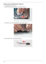
Page 40: ...uetooth Module 1 See Removing the Upper Cover 2 Disconnect the bluetooth cable from the mainboard as shown 3 Using both hands remove the Bluetooth module from the chassis 4 Disconnect the cable from the Bluetooth module ...

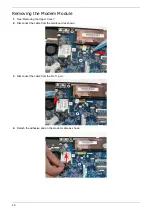
Page 41: ...Removing the Modem Module 1 See Removing the Upper Cover 2 Disconnect the cable from the mainboard as shown 3 Disconnect the cable from the RJ 11 port 4 Detach the adhesive pad on the modem cable as shown ...

Page 42: ...41 5 Disconnect the cable from the Modem module 6 Remove the two securing screws from the Modem module 7 Remove the Modem from the mainboard Step Size Quantity Screw Type Modem Module M2 3 2 ...

Page 43: ...om the mainboard 5 Disconnect the mainboard from the USB Board by lifting the top right corner of the mainboard away from the chassis as shown Step Size Quantity Screw Type Mainboard M2 5 4 1 NOTE Circuit boards 10 cm has been highlighted with the red rectangle as above image shows Please detach the Circuit boards and follow local regulations for disposal ...

Page 44: ...casing to clear the I O ports as shown 7 Lift the mainboard rear edge first as shown and remove from the chassis CAUTION Ensure the I O ports at the bottom of the mainboard are clear of the bottom base to prevent damage to the mainboard ...

Page 45: ...ving the USB Board 1 Remove the mainboard See Removing the Mainboard 2 Remove the two securing screws from the USB board 3 Lift the USB board clear of the chassis Step Size Quantity Screw Type USB Board M2 3 2 ...

Page 46: ...screw 4 to screw 1 from the Thermal Module 3 Using both hands lift the Thermal Module clear of the Mainboard Step Size Quantity Screw Type Thermal Module M M 2 5D 3 2L K 6D NI 4 1 2 3 4 NOTE Battery has been highlighted with the red circle as above image shows Please detach the battery and follow local regulations for disposal ...

Page 47: ... Fan 1 See Removing the Mainboard 2 Disconnect the fan cable from the mainboard 3 Remove the three securing screws from the CPU fan 4 Lift the fan clear of the mainboard Step Size Quantity Screw Type CPU Fan Module M2 4 3 ...

Page 48: ...47 Removing the CPU 1 See Removing the Thermal Module 2 Using a flat screwdriver turn the CPU socket latch counter clockwise 180 to release the CPU 3 Lift the CPU clear of the Mainboard ...

Page 49: ...Module Disassembly Flowchart Screw List Remove Inverter Board Remove LCD Panel Remove LCD Bezel Remove LCD FPC Cable Remove Camera Module Remove LCD Panel from Main Unit before proceeding Remove LCD Brackets Remove Antennas Remove MIC Cable ...

Page 50: ... screws from the LCD module 3 Lift up the bezel left side first as shown followed by the bottom and right sides respectively CAUTION The LCD panel locking latches pass through the top of the bezel Hold the lock in the open position to allow the latches to pass through the bezel when removing the top section Step Size Quantity Screw Type LCD Bezel M2 5 4 4 ...

Page 51: ... the Camera Module 1 Remove the LCD Bezel See Removing the LCD Bezel 2 Disconnect the Camera Module cable as shown 3 Lift the Camera upward to detach the adhesive strip and remove the module from the LCD assembly ...

Page 52: ...l See Removing the LCD Bezel 2 Remove the single securing screw from the Inverter board as shown 3 Lift the Inverter clear of the LCD module and remove the left and right inverter cables from the module Step Size Quantity Screw Type Inverter Board M2 3 1 ...

Page 53: ...moving the Inverter Board 2 Remove the two securing screws from the panel as shown 3 Lift the LCD Panel clear of the LCD Module taking care to ensure the cables are free from the back cover Step Size Quantity Screw Type LCD Panel M2 3 2 ...

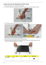
Page 54: ... from the LCD panel as shown 3 Lift the adhesive strip as shown and disconnect the LCD cable interface 4 Grip the FPC cable and lift upward to detach the adhesive pads 5 Remove the eight securing screws four on each side from the LCD Panel brackets Remove the LCD brackets by pulling them away from the LCD Panel Step Size Quantity Screw Type LCD Brackets M2 4 8 ...

Page 55: ...Pack 2 See Removing the 3G Module 3 See Removing the WLAN Module 4 See Removing the LCD Panel 5 Remove the strips holding the antenna cables in place Ensure the cables are free from obstructions 6 Remove the left side antenna cable from the cable channel ...

Page 56: ...strips holding the antenna in place and remove the single securing screw 8 Lift the antenna away from the LCD module 9 Remove the right side antenna cable from the cable channel Step Size Quantity Screw Type WLAN Antenna M2 3 1 ...

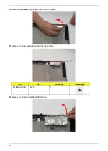
Page 57: ... 10 Detach the adhesive strip holding the antenna in place 11 Remove the single securing screw from the antenna 12 Remove the antenna from the LCD module Step Size Quantity Screw Type WLAN Antenna M2 3 1 ...

Page 58: ...cable from the cable channel 14 Remove the two securing screws from the 3G antenna as shown 15 Remove the 3G antenna from the LCD module as shown and gently remove the adhesive strip Step Size Quantity Screw Type 3G Antenna M2 3 2 ...

Page 59: ...e MIC Module 1 Remove the LCD panel See Removing the LCD Panel 2 Remove the strip holding the MIC Module cable in place Ensure the cable is free from obstructions 3 Remove the MIC cable and Module from the LCD module ...

Reviews: