background image

59

Chapter 3

General Information

Before You Begin

Before proceeding with the disassembly procedure, make sure that you do the following:

1.

Turn off the power to the system and all peripherals.

2.

Unplug the AC adapter and all power and signal cables from the system.

3.

Remove the battery pack.

NOTE: 

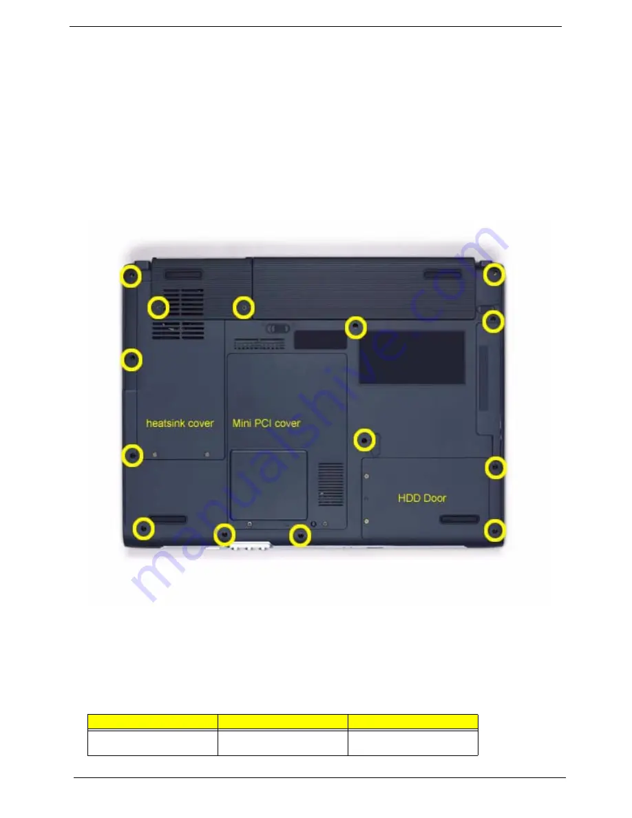
 The screws used to secure bottom case and upper case are more than one type. Please group same 

type of screw together as you disassemble the system for service purpose. The image below is for your 
reference. Please pay attention to the explanation below.

The screws that secure heatsink cover, MIni PCI cover and HDD cover are with the covers. There is no need 
to worry about mix them up. However, please notice that you have to group the screws on the following 
locations together. There are twenty screws holding the bottom case to upper case but some screws are inside 
the system. You may have to remove the HDD, the heatsink cover to see these screws. Mini PCI cover here 
also called RAM/Wireless cover.

Screw Type

Location

Quantity

M2.5*6

Bottom case and IO bezel 
(hightlight with yellow circle)

14

IO Bezel

Battery

Summary of Contents for TravelMate 4100 Series

Page 1: ...100 Aspire 1690 Service Guide PRINTED IN TAIWAN NOTE Please refer to Kestrel Service CD P N VD A27V7 001 Service guide files and updates are available on the ACER CSD web for more information please r...

Page 2: ...to the table below for the updates made on TravelMate 4600 TravelMate 4100 and Aspire 1690 service guide Date Chapter Updates 2005 01 27 CH1 Modify Right Side illustration on page 11 CH3 Modify ODD D...

Page 3: ...ect to the contents hereof and specifically disclaims any warranties of merchantability or fitness for any particular purpose Any Acer Incorporated software described in this manual is sold or license...

Page 4: ...bits and pieces of additional information related to the current topic WARNING Alerts you to any damage that might result from doing or not doing specific actions CAUTION Gives precautionary measures...

Page 5: ...NOT be covered in this generic service guide In such cases please contact your regional offices or the responsible personnel channel to provide you with further technical details 2 Please note WHEN OR...

Page 6: ...9 Hardware Specifications and Configurations 32 Chapter 2 System Utilities 47 BIOS Setup Utility 47 Information 48 Main 49 Advanced 51 Security 53 Boot 56 Exit 57 Chapter 3 Machine Disassembly and Rep...

Page 7: ...80 Index of Error Messages 81 POST Code 84 Index of Symptom to FRU Error Message 85 Intermittent Problems 88 Undetermined Problems 89 Use NAPP CD to Build Master Hard Disc Drive 90 Chpater 5 Jumper a...

Page 8: ...resolution 15 4 WXGA TFT LCD supporting 1280x800 pixel resolution 15 SXGA TFT LCD supporting 1400x1050 pixel resolution Graphics ATI MOBILITYTM RADEON X600 with 64MB of external DDR video RAM supporti...

Page 9: ...10 100M LAN or Giga LAN on board WLAN 802 11b g or 802 11 a b g dual band tri mode Wireless with Mini PCI interface Built in 2 Antenna which has to be placed on the top of LCD on the sides of LCD lat...

Page 10: ...Chapter 1 3 Mainboard Placement Top View...

Page 11: ...4 Chapter 1 Rear View...

Page 12: ...connector CN12 INT MIC connector CN30 PATA HDD connector CN5 Keyboard connector CN31 SATA HDD connector CN6 BT connector CN36 Line IN connector CN8 TP connector CN34 MIC IN connector U4 VGA RAM CN35 L...

Page 13: ...USB4 Page 22 Page 26 MINI PCI BROADCOM CONEXANT 20493 21 MAX9750 Page 28 AMP 20468 31 SPEKER Page 28 Page 27 LINE IN Page 27 MIC IN CONEXANT PS2 HOST BUS 400MHz LPC NS SIO 87383 NS Page 31 Page 31 IrD...

Page 14: ...e support area for your hands when you use the computer 5 Click buttons Left center and right The left and right buttons function like the left and right mouse buttons the center button serves as a 4...

Page 15: ...k buttons Left center and right The left and right buttons function like the left and right mouse buttons the center button serves as a 4 way scroll button 6 Touchpad Touch sensitive pointing device w...

Page 16: ...ion Lights to indicate the status of Bluetooth communications for TM4600 only 6 Wireless communications button indicator Press to enable disable Wireless function Lights to indicate the status of wire...

Page 17: ...e Ejects the optical drive tray when the computer is turned off 4 Optical drive eject button Ejects the optical drive tray from the drive 5 AcerMedia bay for selected models Houses an AcerMedia drive...

Page 18: ...4 in 1 card reader is a manufacturing option subject to configuration Only one card can operate at any given time 5 Two USB 2 0 ports Connect to Universal Serial Bus USB 2 0 devices e g USB mouse USB...

Page 19: ...licator connector for TM4600 only Connects to Acer ezDock 4 Security keylock Connects to a Kensington compatible computer security lock Item Description 1 Power jack Connects to an AC adapter 2 Extern...

Page 20: ...3 AcerMedia bay for TM4600 only Houses an AcerMedia drive module 4 Battery release latch Unlatches the battery to remove the battery pack 5 Battery bay Houses the computer s battery pack 6 Battery lo...

Page 21: ...Unlatches the battery to remove the battery pack 3 Battery bay Houses the computer s battery pack 4 Battery lock Locks the battery in place 5 Cooling fan Helps keep the computer cool NOTE Do not cover...

Page 22: ...ressing the Fn F12 keys simultaneously Lock Key Description Caps Lock When Caps Lock is on all alphabetic characters are typed in uppercase Toggle on and off by pressing the Caps Lock key on the left...

Page 23: ...esired action Num Lock on Num Lock off Number keys on embedded keypad Type numbers in a normal manner Cursor control keys on embedded keypad Hold Shift while using cursor control keys Hold Fn while us...

Page 24: ...onetns TM 4600 TM 4100 AS 1690 The three indicators located above the keyboard provide the following status information NOTE The keypad lock must be turned on to use the embedded numeric keypad Icon I...

Page 25: ...d the state or features can still be seen Icon Item Description Power Lights when the computer is on 1 Charging the light shows amber when the battery is charging 2 Fully charged light shows green whe...

Page 26: ...Chapter 1 19 Windows Keys The keyboard features two keys that perform Windows specific functions TM 4600 TM 4100 AS 1690 y y p p Key Description Tab E F M Shift M R Key Description Tab E F M Shift M R...

Page 27: ...TM 4600 TM 4100 AS 1690 Launch Key Default Application e Acer eManager application user programmable p User programmable Launch Key Default Application e Acer eManager application user programmable p...

Page 28: ...o provide a variety of functions Tab Activates the next Taskbar button E Opens the My Computer window F1 opens Help and Support F opens the Find All Files dialog box M minimizes all windows j Windows...

Page 29: ...ay toggle Switches display output between the display screen external monitor if connected and both the display screen and external monitor Fn F6 Screen blank Turns the display screen backlight off to...

Page 30: ...werManagement ePM Launches the ePowerManagement in the eManager set by the Acer Empowering Key e Fn F4 Sleep Puts the computer in Sleep mode Fn F5 Display toggle Switches display output between the di...

Page 31: ...the computer lets you connect a Kensington compatible computer security lock Wrap a computer security lock cable around an immovable object such as a table or handle of a locked drawer Insert the lock...

Page 32: ...esentation It takes the hassle out of making presentations Acer ePowerManagement It provides a central location from where to control all your PC s power schemes and maximise battery life Acer eRecove...

Page 33: ...aunch Manager allows you to set the two launch keys located above the keyboard You can access the Launch Manager by clicking on Start All Programs and then Launch Manager to start the application Star...

Page 34: ...computer comes with 16 bit high fidelity AC 97 stereo audio and dual stereo speakers TM 4600 TM 4100 AS 1690 Adjusting the Volume Adjusting the volume on the computer is as easy as pressing some butto...

Page 35: ...the keyboard or hold Shift and then press the dollar sign at the upper center of the keyboard AS 1690 1 Open a text editor or word processor 2 Either directly press the Euro symbol at the bottom right...

Page 36: ...e of the palm rest area providing maximum comfort and efficiency Touchpad Basics Use the touchpad as follows Move your finger across the touchpad to move the cursor Press the left 1 and right 3 button...

Page 37: ...uchpad s responsiveness Function Left Button Righ Button Tap Execute Click twice quickly Tap twice at the same speed as double clicking the mouse button Select Click once Tap once Drag Click and hold...

Page 38: ...ptical CD or DVD drive tray To eject the optical drive tray when the computer is turned on press the drive eject button TM 4600 TM 4100 AS 1690 When the power is off you can eject the drive tray using...

Page 39: ...controller Conexant Codec Video controller ATI M24P UMA Hard disk drive controller ICH6 M Keyboard controller KBC 97551 IrDA controller SIO 87383 DVI controller CH7307 PCMCIA card reader 1394 controll...

Page 40: ...above specifications LAN Interface Item Specification Supports LAN protocol 10 100 1000 Mbps Fast Ethernet connection for TM 4600 AS 1690 10 100 Mbps Fast Ethernet connection for TM 4100 only LAN con...

Page 41: ...QL WLP2 0 Mixed sound source CD Sampling rate 48 KHz Internal microphone Yes Internal speaker Quantity Yes 2 PCMCIA Port Item Specification PCMCIA controller PCI7411 Supports card type Type II Number...

Page 42: ...D button Battery Item Specification Vendor model name Panasonic Sanyo Battery Type Li ion Pack capacity 65Wh Cell voltage 3 7V cell 2000mAh High discharge rate Number of battery cell 8 cell 65W 4 cell...

Page 43: ...es Yes Electrical Specification Supply voltage for LCD display V 3 3 3 3 3 3 3 3 3 3 Supply voltage for LCD backlight Vrms 785 785 730 735 735 LCD 15 XGA Item Specifications Vendor model name AU B150X...

Page 44: ...0Hz and 240Vac 50Hz respectively Efficiency High efficiency 85 minimum at 100 240Vac AC input full load warm up condition Output Ratings CV mode DC output voltage Offers constant voltage 19 0V output...

Page 45: ...State S3 CPU Power Down VGA Power Down PCMCIA Suspend Audio Power Down Hard Disk Power Down Super I O Power Down Sleeping State S4 Also called Hibernate state System saves all system states and data o...

Page 46: ...s 12ms 12ms Maximum 22ms 22ms 22ms TOSHIBA Nominal Power Requirements Logic 5V 5V 5V Start 4 7watts 5 0watts 4 7watts Seeking 2 6watts 2 9watts 2 6watts Reading Writing 2 3watts 2 5watts 2 3watts Idle...

Page 47: ...5 500 Hz 9 8 M S2 1 0G 5 500 Hz 9 8 M S2 1 0G 5 500 Hz Operating Shock 200g 200g 200g Non Operating Shock 800g 800g 800g Reliability Characteristics Error Rates Non recoverable 1 in 1013 bits 1 in 10...

Page 48: ...ads physical 2 3 4 3 4 Data disks 1 2 2 2 2 Max areal density Gbits sq inch 70 70 70 70 86 Performance Data buffer MB 2 8 8 8 8 Rotational speed RPM 4 200 4 200 4 200 5 400 5 400 Latency average ms 7...

Page 49: ...Physical size Height mm 9 5 9 5 9 5 9 5 9 5 Width mm 70 70 70 70 70 Depth mm 100 100 100 100 100 Weight typical g 95 99 99 102 102 Environmental characteristics Operating Ambient temperature 5 to 55...

Page 50: ...0 C NA NA Shock half sine wave 800Gs 1ms 800Gs 1ms 800Gs 1ms 1000 G 1 ms 1000 G 1 ms Vibration random RMS 3 01 G 5 500 Hz 3 01 G 5 500 Hz 3 01 G 5 500 Hz NA NA Acoustics A Weighted Sound Power Bels Id...

Page 51: ...cal CHS 16383 16 63 16383 16 63 Recording Method RLL 0 11 RLL 0 11 Reliability Data Integrity Head Rest Method Quick Step Ramp Load Quick Step Ramp Load Nonrecoverable Read Error per Bits Read 1 per 1...

Page 52: ...ombo drive Disc Performance Compatibility DVD Dual Drive Read 24X CD ROM 8X DVD R 8X DVD R 8X DVD ROM 4X DVD RW 4X DVD RW DVD Dual Drive Write 24X CD RW 24X CD R 8X DVD R 8X DVD R 4X DVD RW 4X DVD RW...

Page 53: ...Temperature Operation 5oC Non Operation 20oC DVD CD RW Combo Item Specification Model Name QSI SBW 242 Diameter 12cm and 8cm Capacity CDROM 650 MB mode 1 12cm disk DVDROM 4 7 GB mode 1 12cm disk Tran...

Page 54: ...left right keys zx To choose a parameter use the cursor up down keys wy To change the value of a parameter press p or q Press while you are in any of the menu options to go to the Exit menu In any me...

Page 55: ...orts the BIOS version of system VGA BIOS Version This field reports the VGA version of the system KBC Version Serial Number This item will show the Serial number of system Asset Tag Number This item w...

Page 56: ...only mode Both Simultaneously enable both the integrated LCD screen and the system s external video port for an external CRT or projector Network boot When this is selected Boot from LAN feature is en...

Page 57: ...o Disk recovery Processor Power Management Selects the Processor Power Management desired Disabled C states and GV1 GV3 are disabled GV1 GV3 only C states are disabled C States Only GV1 GV3 are disabl...

Page 58: ...bled Auto Infrared Port Configure serial port B using options Disabled No configuration Enabled User configuration Auto BIOS or OS chooses configuration OS Controlled Displayedd when controlled by OS...

Page 59: ...ation OS Controlled Displayedd when controlled by OS Disabled Enabled Auto Mode Set the mode for the parallel port using options Output only Bi directional EPP ECP Output only Bi directional EPP ECP I...

Page 60: ...sword protects the BIOS Setup Utility from unauthorized access Set System password is set Clear System password is not set Length No more than 8 characters Characters 0 9 A Z not case sensitive Set Us...

Page 61: ...assword currently can not be changed or disabled To change or disable it turn off the system and enter Setup immediately after turning it back on Press Enter to input change or disable hard drive pass...

Page 62: ...OK The password setting is complete after user presses enter If the current password entered does not match the actual current password If the new password and confirm new password strings do not matc...

Page 63: ...only the top device in each category Use F6 and F5 to move highlighted item up and down Floppy Devices CD ROM DVD Drive Netword Boot PhoenixBIOS Setup Utility Info Main Advanced Security Exit Item Spe...

Page 64: ...up data to CMOS Load Setup Default Load default values for all SETUP items Discard Changes Load previous values from CMOS for all SETUP items Save Changes Save Setup Data to CMOS PhoenixBIOS Setup Uti...

Page 65: ...Philips screwdriver Plastic flat head screw driver Tweezers NOTE The screws for the different components vary in size During the disassembly process group the screws with the corresponding components...

Page 66: ...ce purpose The image below is for your reference Please pay attention to the explanation below The screws that secure heatsink cover MIni PCI cover and HDD cover are with the covers There is no need t...

Page 67: ...en you will see 2 M2 5 6 Remove the heatsink cover then you will see 1 M2 5 6 Remove the HDD cover then you will see 1 M2 5 3 Detach the HDD module then you will see 1 M2 5 3 Remove the battery then y...

Page 68: ...emble the inside assembly frame in that order Start Battery HDD Cover ODD Module RAM Wireless Cover E 2 K 2 HDD Module Wireless LAN Card Memory IO Bezel 2 2 Heatsink Cover 2 Thermal Module CPU ODD Con...

Page 69: ...NI NYLOK 86 T23V7 006 SCREW MM25060IL69 86 A08V7 004 SCREW M2 0 5 I NI NYLOK 86 T23V7 010 SCREW M2 0X2 5 I NI NYLOK 86 A03V7 007 SCREW I2 3M NIHY M2L3 86 T25V7 008 SCREW M1 7 3 0 I BK 86 T50V7 001 SC...

Page 70: ...ery Pack NOTE This chapter is base on Aspire 1410 and Aspire 1680 to edit Since they have the similar disassemble and reassemble procedures 1 Unlock the battery lock 2 Slide the battery latch as shown...

Page 71: ...two screws holding the HDD cover 2 Remove the HDD cover 3 Detach the HDD module then remove it Removing the Memory and the Wireless LAN Card 1 Remove the two screws that secure the RAM Wireless cover...

Page 72: ...ove the heatsink cover from the main unit 5 Disconnect the fan cable 6 Remove the four screws that secure the thermal module 7 Pull the thermal module outwards then remove it NOTE The edge of the ther...

Page 73: ...ect the keyboard cable from the main board then remove the keyboard 5 Remove the screw that fastens the ODD module 6 Turn over the notebook computer then detach the ODD module carefully NOTE When you...

Page 74: ...e two screws that secure the keyboard as shown 4 Turn over the keyboard as shown and disconnect the keyboard cable then remove the keyboard 5 Pull out the antenna set with a tweezers then take out the...

Page 75: ...Remove the switch board 3 Disconnect the touchpad FFC from the main board 4 Disconnect the bluetooth cable 5 Remove the five screws that secure the upper case 6 Remove the eighteen screws on the botto...

Page 76: ...cure the touchpad board 5 Remove the touchpad board from the upper case 6 Disconnect the touchpad board to touchpad FFC 7 Remove the touchpad board to touchpad FFC from the uppwer case assembly 8 Remo...

Page 77: ...case 5 Disconnect the speaker cable from the main board 6 Remove the two screws that secure the main board 7 Remove the two screw nuts as shown 8 The you can detach the main board from the upper case...

Page 78: ...71 Chapter 3 13 Then remove another two screws holding the speaker set on the other side 14 Then take out the speaker set from the lower case...

Page 79: ...5 Remove the three screws holding the right hinge 6 Then remove the three screws that secure the left hinge 7 Remove one screw that secure the LCD bracket 8 Remove another screw holding the LCD brack...

Page 80: ...73 Chapter 3 13 Remove the left bracket as the picture shows 14 Tear off the tape fastening the LCD cable 15 Tear off the the LCD cable fastening the LCD cable then remove it...

Page 81: ...lding the HDD bracket on the other side 3 Then take the hard disc drive out from the HDD bracket Disassembling the Optical Drive Module 1 Remove the four screws as the picture shows 2 Remove the two s...

Page 82: ...75 Chapter 3...

Page 83: ...r products Non Acer products prototype cards or modified options can give false errors and invalid system responses 1 Obtain the failing symptoms in as much detail as possible 2 Verify the symptoms by...

Page 84: ...the drive to fail Do the following to select the test device 1 Boot from the diagnostics diskette and start the diagnostics program 2 See if CD ROM Test is passed when the program runs to CD ROM Test...

Page 85: ...DIMM is fully installed into the connector A loose connection can cause an error Power System Check To verify the symptom of the problem power on the computer using each of the following power sources...

Page 86: ...the following Replace the System board If the problem is not corrected see Undetermined Problems on page 89 If the voltage is not correct go to the next step NOTE An audible noise from the power adapt...

Page 87: ...attery pack that has less than 50 of the total power remaining when installed in the computer If the battery status indicator does not light up remove the battery pack and let it return to room temper...

Page 88: ...xt possible FRU to be replaced when servicing a computer If the symptom is not listed see Undetermined Problems on page 89 The following lists the error messages that the BIOS displays on the screen a...

Page 89: ...ult Settings in BIOS Setup Utility Hard disk drive System board Stuck Key see Keyboard or Auxiliary Input Device Check on page 76 Keyboard error see Keyboard or Auxiliary Input Device Check on page 76...

Page 90: ...Setup Utility System cache error Cache disabled System board CPU ID System board DMA Test Failed DIMM System board Software NMI Failed DIMM System board Fail Safe Timer NMI Failed DIMM System board De...

Page 91: ...ource battery pack and power adapter See Power System Check on page 77 Reconnect the LCD connector Hard disk drive LCD inverter ID LCD cable LCD Inverter LCD System board No beep power on indicator tu...

Page 92: ...E7h Go to BIOS E8h Set Huge Segment E9h Initialize Multi Processor EAh Initialize OEM special code EBh Initialize PIC and DMA ECh Initialize Memory type EDh Initialize Memory size EEh Shadow Boot Blo...

Page 93: ...able LCD System board Indicator Related Symptoms Symptom Error Action in Sequence Indicator incorrectly remains off or on but system runs correctly Reconnect the inverter board Inverter board System b...

Page 94: ...hibernation Keyboard if control is from the keyboard Hard disk drive System board The system doesn t enter hibernation mode and four short beeps every minute See Hibernation Mode on page 34 Press Fn...

Page 95: ...Ensure the Parallel Port in the Onboard Devices Configuration of BIOS Setup Utility is set to Enabled Onboard Devices Configuration Run printer self test Printer driver Printer cable Printer System Bo...

Page 96: ...discharge or software errors FRU replacement should be considered only when a recurring problem exists When analyzing an intermittent problem do the following 1 Run the advanced diagnostic test for th...

Page 97: ...lure is operating correctly See Power System Check on page 77 1 Power off the computer 2 Visually check them for damage If any problems are found replace the FRU 3 Remove or disconnect all of the foll...

Page 98: ...Recovery 1 Prepare NAPP CD Recovery CD and System CD 2 Put NAPP CD into the optical drive Then boot up the system 3 The system will ask you if you want to build NAPP Master HDD Please press any key to...

Page 99: ...e This step is to create image files to the system you do not have to put the Recovery CD to the optical drive in order Place one Recovery CD to the drive at one time till you finish all Recovery CDs...

Page 100: ...92 Chapter 4 7 Then insert the System CD to the optical drive 8 You will see the screen displaying PASS when the system has buit NAPP Master hard disc drive...

Page 101: ...PP CD Recovery CD and System CD 2 Put NAPP CD into the optical drive Then boot up the system 3 The system will ask you if you want to build NAPP Master HDD Please press any key to continue 4 NAPP CD w...

Page 102: ...nguages Recovery not more than five languages could be loaded to the system 6 Put the Recovery CD to the optical drive This step is to create image files to the system you do not have to put the Recov...

Page 103: ...Chapter 4 95 After you place the Recovery CD to the optical drive you will see the display below 7 Then insert the System CD to the optical drive...

Page 104: ...96 Chapter 4 8 You will see the screen displaying PASS when the system has buit NAPP Master hard disc drive...

Page 105: ...Chapter 5 97 Top View Jumper and Connector Locations Chapter 5...

Page 106: ...98 Chapter 5 Rear View...

Page 107: ...connector CN12 INT MIC connector CN30 PATA HDD connector CN5 Keyboard connector CN31 SATA HDD connector CN6 BT connector CN36 Line IN connector CN8 TP connector CN34 MIC IN connector U4 VGA RAM CN35 L...

Page 108: ...100 Chapter 5 RTC Jumper...

Page 109: ...number change is made it will not be noted on the printed Service Guide For ACER AUTHORIZED SERVICE PROVIDERS your Acer office may have a DIFFERENT part number code from those given in the FRU list of...

Page 110: ...102 Chapter 6 Exploded Diagram...

Page 111: ...40 ZL1A BATTERY SANYO 8 CELL S P BT T5003 001 BATTERY PANASONIC LI ION 4S2P 4 4A CGR B 8B5AE ZL1A BATTERY PANASONIC 8 CELL S P BT T5005 001 BATTERY SIMPLO LI ION 4S2P 4 4A 916 3020 ZL1A BATTERY SIMPLO...

Page 112: ...006 POWER CORD EU 3 PIN ET2S POWER CORD S P EU 27 A03V7 002 POWER CORD UK 3 PIN ET2S POWER CORD S P UK 27 A03V7 004 POWER CORD ITALIAN 3 PIN ET2S POWER CORD S P ITALIAN 27 A03V7 005 POWER CORD SWISS...

Page 113: ...42 T63V7 004 HDD BRACKET ZL1A HDD BRACKET ASSY S P 33 T50V7 001 Communication Module WIRELESS LAN ANTENNA ZL1A WIRELESS ANTENNA ASSY S P 50 T50V7 003 CPU Processor INTEL PENTIUM M 1 5G 2M 400FSB uFCP...

Page 114: ...DRW BEZEL FOR KME ZL1A COMBO BEZEL KME ASSY S P 42 T50V7 009 DVD DUAL MODULE QSI SDW 082 SWAP ZL2 DVD DUAL QSI SDW 082 W MB ASSY S P TBD DVD DUAL DRIVE QSI SDW 082 F W ZL1A DVD DUAL QSI SDW 082 S P TB...

Page 115: ...08210A KH 08001 012 TOSHIBA PROTEUS 60GB 5400RPM MK6026GAX PA202G TOSHIBA PROTEUS 80GB 5400RPM MK8026GAX KH 06004 002 HGST MORAGA 60GB 5400RPM HTS541060G9AT00 A56J HGST MORAGA 60GB 5400RPM HTS541060G9...

Page 116: ...RFON Sweden ZL1A K B EUGO SWEDEN ASSY S P KB T5007 015 TM4500 TM4000 TM2300 KEYBOARD DARFON Czech ZL1A K B EUGO CZECH ASSY S P KB T5007 016 TM4500 TM4000 TM2300 KEYBOARD DARFON Hungaian ZL1A K B EUGO...

Page 117: ...P 60 T50V7 004 LCD PANEL W LOGO ANTENNA 14 15 IN LIGHT GREEN SILVER ZL1A 14 15 LCD COVER TM ASSY S P NEW COLOR 60 T50V7 102 LCD MODULE 15 IN SXGA AU B150PG03 LIGHT GREEN SILVER ZL1 15 LCD SXGA TM AU...

Page 118: ...14 15 IN LIGHT GREEN SILVER ZL1A 14 15 LCD COVER TM ASSY S P NEW COLOR 60 T50V7 102 LCD MODULE 15 4 IN WXGA QDI QD15TL02 01 LIGHT GREEN SILVER ZL1A 15 4 LCD WXGA TM QDI ASSY S P NEW COLOR 6M T50V7 02...

Page 119: ...15 4 IN LIGHT GREEN SILVER ZL1A 15 4 LCD TM COVER ASSY S P NEW COLOR 60 T50V7 103 LCD MODULE 15 4 IN WXGA CMO N154I1 L09 V C2 LIGHT GREEN SILVER ZL2 15 4 LCD WXGA TM CMO ASSY S P NEW COLOR 6M T63V7 0...

Page 120: ...5 4 IN WXGA HITACHI TX39D85VC1FAA LIGHT GREEN SILVER ZL1A 15 4 LCD WXGA TM HITACHI ASSY S P NEW COLOR 6M T63V7 015 LCD 15 4 IN WXGA HITACHI TX39D85VC1FAA ZL2 15 4 LCD HITACHI PANEL ASSY S P LK 15404 0...

Page 121: ...11u KN 51204 013 MEMORY DDR333 512MB SAMSUNG M470L6524BT0 CB3 MEMORY DDR333 512MB SAMSUNG M470L6524BT0 CB3 KN 5120B 006 SO DIMM DDR333 512MB UNIFOSA U30512AAUIQ652AW20 SO DIMM DDR333 512MB UNIFOSA U3...

Page 122: ...5 3M BNIH M2 5L3 ZG1S I2 5 3M BNIH M2 5L3 S P 86 T25V7 012 SCREW M2 5 4L BZN NYLOK ET2S SCREW MM2 5X4 0 SPARE PART 86 A03V7 006 SCREW M2 0X5 I NI NYLOK ZI1S SCREW M2 0X5 I NI NYLOK S P 86 T23V7 006 SC...

Page 123: ...3 1x256MB 60GB 24x Combo Intel220 0BG Li lon Crane 8cell ATI M24P 64MB TM4101L PM730 15 0 XGA DDR333 1x256MB 60GB 24x Combo Intel220 0BG Li lon Crane 8cell ATI M24P 64MB Model Number CPU LCD Memory HD...

Page 124: ...Home environment Refer to the following lists for components adapter cards and peripherals which have passed these tests Regarding configuration combination and test procedures please refer to the Tra...

Page 125: ...1M 400M FSB Mobile Intel Celeron M 400MHz FSB Regular uFCPGA 512KB L2 Intel Celeron M 370 1 5GHz 1M 400M FSB LCD 15 XGA LCD SPWG B 170nits typ XGA AU B150XG02 V 2 SPWG B 160nits typ XGA LG LP150X08 A3...

Page 126: ...2MB HDD 60GB 2 5 4200rpm HGST Moraga IC25N060ATMR04 0 08K0634 2 5 4200rpm TOSHIBA Pluto MK6025GAS 2 5 4200rpm Seagate N2 50 ST960821A HDD 80GB 2 5 4200rpm HGST Moraga IC25N080ATMR04 0 08K635 2 5 4200r...

Page 127: ...4UR18650F QC141 ZL1 4S1P 2 2A AHA44122A01 Battery Li Ion Panasonic Panasonic Li Ion 4 Cell CGR B 423AE ZL1 4S1P 14 8V 2 2A AHA44122712 Battery Li Ion Simplo Simplo Li Ion 4 Cell 916 2990 4S1P 2 2A AHA...

Page 128: ...on on all of Acer s Notebook Desktop and Server models including Service guides for all models User s manuals Training materials Bios updates Software utilities Spare parts lists TABs Technical Announ...

Reviews: