background image


25 

ACER S230HL


Go to contents page                  

4. Assembly and Disassembly Procedures


4.1  Assembly Procedures

pure A monitor

:


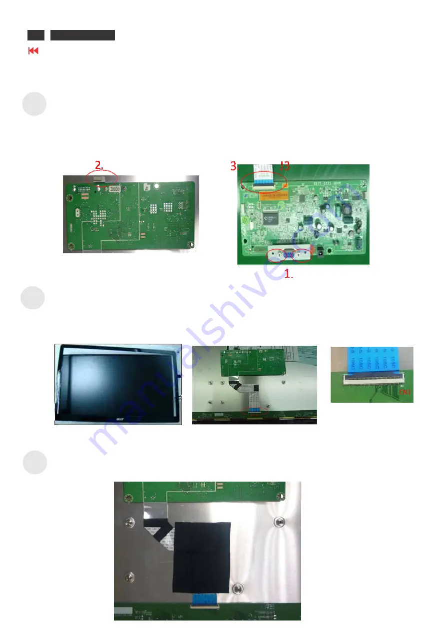
S1     

1.


Tightening the bracket of D-Sub on the Main board with two HEX-head screws. 

                         (The HEX-head screw size = MAC. SCREW-MHSW #4-40*5.0L,Ni)


2. 

Sticking the gasket on the bottom of bracket of D-Sub. 

                         (Gasket size = 5.0W*3.5H*10.0Lmm) 


3.


Connecting LVDS cable to J3 connector of Main board. 


S2            

1:


Putting the Panel on the protective cushion and let the glass side of panel face us. Then cover it with  

Front Bezel  

2: 

Turning over the panel.Put the main board on it and plug LVDS cable to CN1 connector of source  

board (T-con). 


S3    

Using Acetate cloth tape to stick LVDS cable on the Panel firmly. (ACETATE CLOTH TAPE size= 60*80mm


Summary of Contents for S230HL

Page 1: ...ACER_LCD__S230HL ...

Page 2: ...edures 25 05 Troubleshooting 44 06 Firmware Upgrade Procedure 47 07 Writing EDID Procedure 49 08 FRU Field Replaceable Unit List 52 09 Schematics and Layouts 54 Safety Notice Any person attempting to service this chassis must familiarize with the chassis and be aware of the necessary safety precautions to be used when serving electronic equipment containing high voltage ...

Page 3: ...mproper repairing method may damage equipment or products It is recommended that service engineers should have repairing knowledge experience as well as appropriate product training per new model before performing the service procedures NOTICE To avoid electrical shocks the products should be connect to an authorized power cord and turn off the master power switch each time before removing the AC ...

Page 4: ...complies with the VESA DPMS Display Power Management Standard General display parameters Optical Characteristics 1 2 General Requirements 1 2 1 Test Condition Normal test condition is that brightness level set at Max and contrast level set default Test pattern is full white pattern The warm up time is more than 30 minutes Ambient light should be less than 1 Lux 1 2 2 Test Equipment The reference s...

Page 5: ...ation ACER S230HL 3 Go to contents page 1 3 Electrical This section describes the electrical requirement of the pure A and A D monitor Below is the pure A monitor s block diagram And below is A D monitor s block diagram ...

Page 6: ...TEM SPEC Frequency Ranges H 30kHz 83kHz V 56Hz 75Hz Max Pixel clock 173MHz RGB Input Level 0 7Vp p RGB Input Impedance 75 Ω Sync Input Signal Separate SYNC Analog Signal Input Sync Input Impedance 2 2K Ω Frequency Ranges H 30kHz 83kHz V 56Hz 75Hz Max Pixel clock 165MHz Input Level 150mV Vp p 1560mV Input Impedance 100Ω DVI Digital Video Interface HDCP HDCP 1 0 DC Jack power adaptor 19V 2 1A Connec...

Page 7: ...video B Key Board connector Key Board connector J1 Pin Signal Descript ion Pin Signal Descript ion 1 Key1 ADC1 5 LED_CONN LED blue control 2 Key2 ADC2 6 GND Ground 3 PWR_KEY Power On Off control 7 3V3D_REG 3 3V supply power 4 NC No connection C Backlight connector Backlight connector BJ1 Pin Signal Descript ion Pin Signal Descript ion 1 LED_ST2 6 VDD_LEDDRV 2 NC No connection 7 NC No connection 3 ...

Page 8: ...E Clock3 20 POL2 Polarity Control Signal 45 CLK3 GIP GATE Clock3 21 POL Polarity Control Signal 46 CLK2 GIP GATE Clock2 22 CSC Charge Share mode control Signal 47 CLK2 GIP GATE Clock2 23 H2DOT Horizontal 2 Inversion Sognal 48 CLK1 GIP GATE Clock1 24 ICLK_REST Vertical Start Plus 49 CLK1 GIP GATE Clock1 25 GND Ground 50 GND Ground b Input signal connector of LED Backlight power Pin Signal Descript ...

Page 9: ...e monitor actually detects a logic 0 shall be at least 0 3 volt lower than the level at which it actually detects a logic 1 If the monitor sync processing circuits were designed with 3 3 volt logic family then the sync inputs must be 5 volt tolerant 1 3 2 5 Sync Signal Loading TTL input loading shall be equivalent to one TTL input load When logic 0 is asserted by a sync input the maximum current s...

Page 10: ... between OSD items and increase the value of sliding bar 6 Power After AC on by plugging in a power cord and pressing Power button LED indicator turns to blue to indicate power on To turn off this device press this button again B Menu Operation Pressing the MENU button brings up the first level menu This menu button is used to enter the second OSD menu also 1s t Sub Menu 2nd Sub Menu 3r d Sub Menu...

Page 11: ... pull up resistor on a ground pin to determine if the video cable is connected to the PC D OSD Control Factory Default Values The OSD controls shall have the following factory default values Brightness 100 Contrast 50 Color Temperature Warm 6500 Cool 9300 User R G B all are 100 Horizontal Position of Screen Hor 50 Ver 50 OSD Timeout 10 seconds OSD Language English 1 3 4 Monitor Modes and Timing Ca...

Page 12: ... 63Hz Power Consumption Power consumption for the monitor shall be less than 30W over the specified voltage and frequency ranges In power off mode the power consumption will be less than 0 6W at 110VAC Lin e Fuse The AC input shall be fused and become electrically open as a result on an unsafe current level The fuse may not user replaceable Initial Cold Start The power adaptor shall start and func...

Page 13: ... the light guide that sputtering over the life of the lamps shall not cause degradation of the luminance uniformity such as non illuminated bands along the edges of the display 1 4 5 Defects 1 4 5 1 Visual Inspection The LCD panel shall be inspected with all pixels set to white black red green and blue The color variation brightness variation and overall appearance must meet the SPEC 1 4 5 2 Displ...

Page 14: ...ot vary in size or intensity contrast when contrast voltage is varied Contrast variation can be achieved through the use of varying gray shade patterns Polarizer Scratch When the unit lights lines appear light white with display patterns dark and do not vary in size Physical damage to the polarizer does not damage the glass Polarizer Dent When the unit lights spots appear light white with display ...

Page 15: ...ACER S230HL 13 Go to contents page 1 Product Specification Polarizer Defects ...

Page 16: ...rast ratio is determined by using a photometer CA 210 to measure the maximum and minimum luminance in front of monitor after at least 30 minutes warm up It shall be test at 1920x1080 60Hz mode and full white full black square pattern with contrast brightness in default value The values specified are at an approximate distance 50cm from the LCD surface and at 0 viewing angle The contrast ratio is c...

Page 17: ...angles are measured at CR 10 as below Horizontal Left 85 degrees typ Right 85 degrees typ Vertical Up 75 degrees typ Down 85 degrees typ 1 5 5 Chromaticity The color chromaticity is measured by a photometer CA 210 at 1920x1080 60Hz mode and full white square pattern with contrast brightness in default value The x and y co ordinates for Reddish Bluish and User preset mode shall be as below Reddish ...

Page 18: ...creen black pattern luminance at center should be 1cd m 1 6 Environmental Requirements 1 6 1 Temperature Ranges Operating Temperature 5 C to 35 C Shipping Temperature 25 C to 60 C Storage Temperature 25 C to 60 C 1 6 2 Humidity Operating non condensing 20 to 80 Shipping non condensing 10 to 90 Storage non condensing 10 to 90 1 7 Mechanical and Packing H eight including stand 383 7mm 333 2mm w itho...

Page 19: ...nction Menu or sub menu EXIT AUTO Adjust function E Empowering Menu or sub menu EXIT SCENARIO mode Picture OSD 17 ACER S230HL Go to contents page 2 OSD Menu 2 1 Key Definition 2 2 Function Menu 1 Display Function Menu while user press any function button 2 Layout as following figure 2 3 Main OSD Menu 2 3 1 OSD layout a Display OSD menu when user press MENU button on front bezel b Layout as followi...

Page 20: ...ge e Item page status Status Display type Non focus Item focused Item selected 2 3 2 Key operation a Key operation at function icon Key F unction description Power Power off the monitor a Moving the focus down b Moving the focus up c Enter to the item page 1 It has no function at the information page d Exit the OSD menu e Trigger the acer eColor Management E D C B A ...

Page 21: ...b Moving the focus up c Select function item for adjustment d Exit from the item page to icon place e Trigger the acer eColor Management E D C B A d Key operation at items page item selected Key F unction description Power Power off the monitor a Increase the setting value for target item b Decrease the setting value for target item c No function d Exit from item selected status e Trigger the acer...

Page 22: ...ving Please Wait After user trigger the reset function system will show this message notice user the reset is in proceeding 2 7 OSD Menu Tree 1 s t Sub Menu 2 nd S ub Menu 3 r d Sub M enu 4 r d Sub Menu V alue VGA HDMI Remark A cer Color management v v Brightness Slider 100 0 100 1 v v Contrast Slider 50 0 100 1 v v H Position Slider 50 10 0 1 v V Position Slider 50 10 0 1 v Focus Slider 50 0 100 ...

Page 23: ...21 ACER S230HL Go to contents page 3 Exploded Diagram 3 1 1 Product Exploded Diagram pure A monitor ...

Page 24: ...3 Exploded Diagram ACER S230HL 22 Go to contents page 3 1 2 Packing Exploded Diagram pure A monitor ...

Page 25: ...23 ACER S230HL Go to contents page 3 Exploded Diagram 3 2 1 Product Exploded Diagram A D monitor ...

Page 26: ...T Y PART DESCRIPTION REMARK 1 1 CARTON 1925 1001 1070 EPS TOP 2 1 1925 1001 1080 EPS BOTTOM 3 1 1925 1100 4120 EPE BAG 4 TAP 5 1 USER S MANUAL GUARANTEE CARD 6 1 3522 0042 0300 LCD MONITOR 7 1 1801 0540 5010 NECK 8 1 1801 0540 4010 BASE 9 1 POWER CABLE 10 1 SIGNAL CABLE 11 1 ADAPTER CABLE 12 1 DVI CABLE ...

Page 27: ...e gasket on the bottom of bracket of D Sub Gasket size 5 0W 3 5H 10 0Lmm 3 Connecting LVDS cable to J3 connector of Main board S2 1 Putting the Panel on the protective cushion and let the glass side of panel face us Then cover it with Front Bezel 2 Turning over the panel Put the main board on it and plug LVDS cable to CN1 connector of source board T con S3 Using Acetate cloth tape to stick LVDS ca...

Page 28: ...connector of Panel with the Panel power cable FFC cable 2 Using the two kinds of Acetate cloth tapes to stick the Panel power cable on the Panel Tape 1 20 45 Tape 2 12 30mm S6 1 Taking the wire cable to connect the J1 connector of Main board and J1 connector of OSD key board 2 Using one Acetate cloth tape to stick wire cable ACETATE CLOTH TAPE 21 61mm 3 Putting the OSD key assembly into the hooks ...

Page 29: ... to make the hook structure assembled well S8 Using the Phillips head screwdriver to tighten bracket of D sub for fixing on the Rear Cover with two M3 screws Screw size MAC SCREW MB M3 0 5 0L BLK Ni Torque 4 1kgf cm S9 1 Putting the Neck into the holes of Rear Cover s bottom area as red square of area shown 2 Pushing the neck as red arrow shown ...

Page 30: ...ction Turn off the monitor and remove the signal cable and power cord from the monitor 2 Removing the base unit and neck one separately from the monitor assembly Then take a EPE bag to cover the LCD monitor The words of welcome to Acer of EPE bag must be toward front S12 1 Putting down Monitor assembly of unit on the EPS Bottom before putting specific carton 2 Placing the folding power cable and t...

Page 31: ...29 ACER S230HL Go to contents page 4 Assembly and Disassembly Procedures S13 S14 To seal up the carton ...

Page 32: ... of Main board S2 1 Putting the Panel on the protective cushion and let the glass side of panel face us Then cover it with Front Bezel 2 Turning over the panel Put the main board on it and plug LVDS cable to CN1 connector of source board T con S3 Using Acetate cloth tape to stick LVDS cable on the Panel firmly ACETATE CLOTH TAPE size 60 80mm 1 2 1 J3 ...

Page 33: ...FC cable 2 Using the two kinds of Acetate cloth tapes to stick the Panel power cable on the Panel Tape 1 20 45 Tape 2 12 30mm S6 1 Taking the wire cable to connect the J1 connector of Main board and J1 connector of OSD key board 2 Using one Aluminium tape to stick wire cable ALUMINIUM TAPE 21 61mm 3 Putting the OSD key assembly into the hooks of Front Bezel firmly Don t let the wire cable touch th...

Page 34: ... the bracket of D Sub DVI on the Main board with four HEX head screws The HEX head screw size MAC SCREW MHSW 4 40 5 0L Ni 2 Using the Phillips head screwdriver to tighten 4 screws to fix Main board and shielding cover on the Panel s UDM MAC SCREW MB M3 0 5 0L BLK Ni Torque 5 1kgf cm 2 2 1 ...

Page 35: ... to make the hook structure assembled well S9 Using the Phillips head screwdriver to tighten bracket of D sub for fixing on the Rear Cover with two M3 screws Screw size MAC SCREW MB M3 0 5 0L BLK Ni Torque 4 1kgf cm S10 1 Putting the Neck into the holes of Rear Cover s bottom area as red square of area shown 2 Pushing the neck as red arrow shown ...

Page 36: ... the signal cable and power cord from the monitor 2 Removing the base unit and neck one separately from the monitor assembly Then take a EPE bag to cover the LCD monitor The words of welcome to Acer of EPE bag must be toward front S13 1 Putting down Monitor assembly of unit on the EPS Bottom before putting specific carton 2 Placing the folding power cable and the folding signal cable in EPS Bottom...

Page 37: ...35 ACER S230HL Go to contents page 4 Assembly and Disassembly Procedures S14 S15 To seal up the carton ...

Page 38: ...sembly after removing all EPS from the LCD monitor assembly S3 1 Because the Neck unit and Base unit already separated from taking out from carton So it does not have to disassemble these units 2 Preparing the protective cushion to put on working desk and let the LCD monitor assembly to lie it down 3 Using a Phillips head screwdriver to release the two screws from the Rear cover in anticlockwise w...

Page 39: ...rd separate the connector of the Panel power cable from the connector of panel and the connector of main Board Tape 1 20 45 Tape 2 12 30mm S5 1 Tearing the Acetate cloth tapes from the wire cable of OSD key ACETATE CLOTH TAPE 21 61mm 2 Separating the connector of wire cable of OSD key from the connector of main board ...

Page 40: ... Phillips head screwdriver to release the four screws from the Panel in anticlockwise way MAC SCREW MB M3 0 5 0L BLK Ni Torque 5 1kgf cm 2 Afterward tearing the Acetate cloth tapes from the LVDS cable S7 Separating the connector of LVDS cable from the connector of source board of panel ...

Page 41: ...39 ACER S230HL Go to contents page 4 Assembly and Disassembly Procedures S8 1 Turning over the last module and take away the Front Bezel 2 Leaving the Panel module on the protective cushion ...

Page 42: ...mbly after removing all EPS from the LCD monitor assembly S3 1 Because the Neck unit and Base unit already separated from taking out from carton So it does not have to disassemble these units 2 Preparing the protective cushion to put on working desk and let the LCD monitor assembly to lie it down 3 Using a Phillips head screwdriver to release the two screws from the Rear cover in anticlockwise way...

Page 43: ...ward separate the connector of the Panel power cable from the connector of panel and the connector of main Board Tape 1 20 45 Tape 2 12 30mm S5 1 Tearing the Aluminium tapes from the wire cable of OSD key ALUMINIUM TAPE 21 61mm 2 Separating the connector of wire cable of OSD key from the connector of main board 1 2 ...

Page 44: ...hillips head screwdriver to release the four screws from the Panel in anticlockwise way MAC SCREW MB M3 0 5 0L BLK Ni Torque 5 1kgf cm 2 Afterward tearing the Acetate cloth tapes from the LVDS cable S7 Separating the connector of LVDS cable from the connector of source board of panel 2 1 ...

Page 45: ...43 ACER S230HL Go to contents page 4 Assembly and Disassembly Procedures S8 1 Turning over the last module and take away the Front Bezel 2 Leaving the Panel module on the protective cushion ...

Page 46: ... normal End 1 Check AC power is supplied to DC adaptor 2 Press power button 3 Check key board wire is connected property Check ACER logo display at begin Check LED backlight is working Refer to LED backlight debug section Refer to power debug section Yes Yes Yes Yes No No No No Yes Check 50 pins FFC cable is connected property Reconnect 50 pins FFC between main board and LCM No Yes ...

Page 47: ...45 ACER S230HL 5 Troubleshooting ACER HS244HQ Go to contents pages 5 2 LED backlight debug flow ...

Page 48: ...roubleshooting Go to contents page 5 3 Power debug flow Check L1 pin2 is about 5 1V U2 is defect Check U1 pin2 is about 3 3V U1 is defect Check U3 pin2 is about 1 8V U3 is defect Check TCE46 pin1 is about 12 4V TU3 is defect Start End ...

Page 49: ...6 1 1 Hardware Required S230HL set 1pcs PC with Windows XP D sub cable 1pcs USB cable 1pcs S230HL set 1 pcs Mstar ISP Board 1 pcs D sub Cable 1pcs USB Cable 1pcs 6 1 2 Software Preparation Mstar utility ISP_Tool exe Latest firmware binary files 6 2 Hardware Configuration Connect USB to PC host for ISP Programming Connect D sub to monitor for ISP Programming MSTAR ISP BOARD ...

Page 50: ...ction The message OK stands for connection successful S4 Press Read button for loading the binary file S5 Select Auto button for entering download menu then press Run button for updating firmware Once you see the message of Pass shown on the window it means firmware update is finished 6 4 How to Check firmware version S1 Turn off the monitor press Power and e button at the same time for turning on...

Page 51: ... Hardware Configuration Please reference chapter 6 2 7 2 EDID Generator Operation S1 Press Load button and select the binary file which is prepared to update to EEPROM S2 Check Config setting to 128 Bytes S3 Press Write Button to write EDID data EEPROM verify Function show Pass message ...

Page 52: ...ower Key in Power Off ii Select F Item in Menu Menu Figure 1 Main Menu with Factory Mode Enabled Figure 2 Factory Menu B Go To Region Item and Select according the following table Figure 3 Language Set Note Please Do NOT Change any Other Value in Factory Mode Unless mentioned in Service Menu Value Language Set 0 EMEA 1 Non EMEA 2 Russia ...

Page 53: ...How to Calibration Auto Color For VGA Port C Enter Factory Mode Mentioned in Section 0 D Input 5 Mosaic Pattern in VGA Port E Press Auto Color Item Figure 4 5 Mosaic Pattern Note Please Do NOT Change any Other Value in Factory Mode Unless mentioned in Service Menu ...

Page 54: ...by your regional Acer office to order FRU parts for repair and service of customer machines NOTE T o scrap or to return the defective parts you should follow the local government ordinance or regulations on how to dispose it properly or follow the rules set by your regional Acer office on how to return it Category Part Name Description ACER Part No ADAPTOR 30070131012 Adapter DELTA 40W 19V 1 7x5 5...

Page 55: ...K0K 004 CASE COVER BRACKET ASSEMBLY 180105404011 BASE ASSY W RUBER 60 LTK0K 001 180105405011 NICK ASSY 60 LTK0K 002 180102335010 REAR COVER ASSY 60 LTS0K 001 180102335020 REAR COVER ASSY FOR VGA DVI 60 LTS0K 002 17120102095 MAIN SHIELDING FOR VGA DVI 33 LTK0K 001 170104231010 KEY PAD 42 LTK0K 001 LCD 352350020395 LED LCD LPL 23 W FHD None Glare LM230WF5 TJA1 LF 250nit 5ms W FRONT BEZEL LK 23008 02...

Page 56: ...09 Schematics and Layouts ACER S230HL 54 Go to contents page ACER S230HL 41 ...

Page 57: ...55 ACER S230HL ACER S230HL 42 Go to contents page ACER S230 09 Schematics and Layouts ...

Page 58: ...ACER S230HL 56 L 09 Schematics and Layouts Go to contents page ACER S230HL ...

Page 59: ...57 ACER S230HL ACER S230HL Go to contents page ACER S230 09 Schematics and Layouts ...

Page 60: ...ACER S230HL 58 09 Schematics and Layouts Go to contents page ...

Page 61: ...59 ACER S230HL ACER S230HL Go to contents page 09 Schematics and Layouts ...

Page 62: ...ACER S230HL 60 S230 09 Schematics and Layouts Go to contents page ...

Page 63: ...61 ACER S230HL ACER S230 47 Go to contents page 09 Schematics and Layouts ...

Page 64: ...ACER S230HL 62 ACER S230HL Go to contents page Pure A monitor PCB Layout 1 TOP Side 2 Bottom Side ...

Page 65: ...ACER S230HL 63 Go to contents page A D monitor PCB Layout 1 TOP Side 2 Bottom Side ...

Reviews: