background image

Chapter 3

28

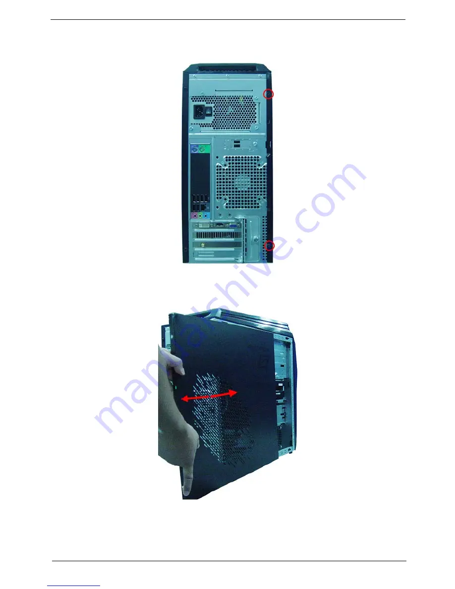
Removing the Side Panel

1.

Remove the two screws located on the rear edge of the side panel.

2.

Slide the side panel toward the back of the chassis until the tabs on the cover disengage with the slots on 
the chassis. 

3.

Lift the side panel away from the server and put it aside for reinstallation later.


Summary of Contents for PREDATOR G5900

Page 1: ...i Acer Predator G5900 Service Guide PRINTED IN TAIWAN ...

Page 2: ...ii Revision History Please refer to the table below for the updates made on this service guide Date Chapter Updates ...

Page 3: ...ublication may be reproduced transmitted transcribed stored in a retrieval system or translated into any language or computer language in any form or by any means electronic mechanical magnetic optical chemical manual or otherwise without the prior written permission of Acer Incorporated ...

Page 4: ... programs prove defective following their purchase the buyer and not Acer Incorporated its distributor or its dealer assumes the entire cost of all necessary servicing repair and any incidental or consequential damages resulting from any defect in the software Acer is a registered trademark of Acer Corporation Intel is a registered trademark of Intel Corporation Pentium Dual Core Celeron Dual Core...

Page 5: ...ditional information related to the current topic WARNING Alerts you to any physical risk or system damage that might result from doing or not doing specific actions CAUTION Gives precautionary measures to avoid possible hardware or software problems IMPORTANT Reminds you to do specific actions relevant to the accomplishment of procedures ...

Page 6: ...h cases please contact your regional offices or the responsible personnel channel to provide you with further technical details FRU Information Please note WHEN ORDERING FRU PARTS that you should check the most up to date information available on your regional web or channel If for whatever reason a part number change is made it will not be noted in the printed Service Guide For ACER AUTHORIZED SE...

Page 7: ...less Card 35 Removing the Memory Modules 36 Removing the System Fan 37 Removing the Daughter Board 38 Removing Other Side Panel 40 Removing the Hard Disk Drive 41 Removing the Removable Hard Disk Drive 43 Removing the Optical Drive 46 Removing the Power Supply 48 Removing the Motherboard 49 Removing the Card Reader 52 Removing the Top Cover 54 Removing the Power Switch and LED Cable Assembly 55 Re...

Page 8: ...iii FRU Field Replaceable Unit List 74 Predator G5900 Exploded Diagram 75 Predator G5900 FRU List 77 Inter RIAD SOP 82 Inter Matrix Storage Technology Check For Dos 82 Inter RAID SOP Windows for WIN7 87 ...

Page 9: ...4mm 4 Layers Memory subsystem DDR3 4 Design requirement 2 channels 2 DIMMs per channel Different colors for DIMM 0 and DIMM 1 Dual channel should be enabled always when plug in 2 same memory size DDRIII memory module Max memory of 16 GB supported using 4Gb tech Support DDR3 1 5V 1066 1333 1GB 2GB 4GB Must meet Intel Lynnfield and Clarkdale Chipset platform design guide Hard disk drive Support up t...

Page 10: ...ated on rear panel and others located on front bezel and top bezel Expansion Slots 1 PCIex16 slot 2 PCIex1 slots 1 PCI slot Serial ATA controller Connector Type SATA connector Connector Quantity 6 Storage Type support HDD Support RAID 0 1 5 10 Blue Ray ODD AHCI mode supported for internal SATA port Rear I O connectors 1 PS 2 keyboard PS 2 mouse connector 6 USB ports 1 RJ45 LAN connector 1 Audio po...

Page 11: ...define 1 H1X4 CPU with SAMRT FAN controller 1 H1X3 System with SAMRT FAN controller 1 H1X4 SPDIFOUT Header for Acer pin define 1 H3X1 Clear CMOS Header with jumper 1 onboard Buzzer 2 H1X2 GPIO header System BIOS Kernel AMI Kernel with Acer skin Size 2Mb Power supply FR500W FR750W EUP lot6 ...

Page 12: ...4 Chapter 1 Block Diagram ...

Page 13: ...O slot 3 Master optical drive crab 10 SD MMC Secure Digital MultiMedia Card slot 4 Slave optical drive crab 11 Master optical drive button Press to open master optical drive crab and access the master optical drive 5 XD XD Picture slot 12 Slave optical drive button Press to open slave optical drive crab and access the slave optical drive 6 Micro SD slot 13 Microphone in jack 7 CF I II CompactFlash...

Page 14: ...rd port 3 USB 2 0 ports 4 Line out jack 5 Microphone speaker out line in jack 6 Expansion slot graphics card and Mode card etc 7 Line in jack 8 RJ45 LAN connector 9 System Fan 10 PS2 mouse port Line out jack 11 USB 2 0 ports 12 Power switch 1 3 6 8 4 5 2 7 9 10 11 12 ...

Page 15: ...SMBIOS 2 6 PCI2 3 PCIE1 1 PCIE2 0 USB2 0 Device Boot Support Support BBS spec 1st priority HDD 2nd priority CD DVD 3th priority Removable device 4th priority LAN Support to LS 120 drive YES Support to BIOS boot block feature YES Hotkey Function Description Del Enter BIOS Setup Utility Press while the system is booting to enter BIOS Setup Utility Item Specification North Bridge Intel H57 Audio cont...

Page 16: ...memory modules in any combination as long as they match the above specifications Item Specification Audio controller Realtek ALC662VC 0 Audio controller type HD Audio Audio channel codec 5 1 Audio function control Enable disable by BIOS Setup Mono or stereo Stereo Compatibility Support host audio controller from the Intel ICH series chipset and also from any other HDA compatible audio controller W...

Page 17: ...antity 6 USB ports located on rear panel 2 USB for the DB on rear side others located on front bezel and top bezel Item Specification Temperature Operating 5 C 35 C Non operating 20 60 C Storage package Humidity Operating 15 to 80 RH Non operating 10 to 90 RH Vibration Operating unpacked 5 500 Hz 2 20g RMS random 10 minutes per axis in all 3 axes 5 500 Hz 1 09g RMS random 1 hour per axis in all 3 ...

Page 18: ...external switch Button modem ring in keyboard an mouse for APM mode Resume recovery time 7 10sec Suspend Mode Independent power management timer 2 120minutes time step 10minute or pushing extern switch button CPU goes into SMM CPU asserts STPCLK and goes into the Stop Grant State LED on panel turns amber colour Hard disk drive goes into SLEEP mode for ATA standard interface Disable H sync and V sy...

Page 19: ...rompted Run Setup message to make changes to the CMOS setup NOTE If you repeatedly receive Run Setup messages the battery may be bad In this case the system cannot retain configuration values in CMOS Ask a qualified technician for assistance CMOS setup loads the configuration values in a battery backed nonvolatile memory called CMOS RAM This memory area is not part of the system RAM which allows c...

Page 20: ...page of a multiple page menu Home Move the cursor to the first page of a multiple page menu End Move the cursor to the last page of a multiple page menu and keys Select a value for the currently selected field only if it is user configurable Press these keys repeatedly to display each possible entry or the Enter key to choose from a pop up menu NOTE Grayed out fields are not user configurable Ente...

Page 21: ...tup page includes all advanced chipset features Integrated Peripherals This setup page includes all onboard peripherals Power Management Setup This setup page includes all the items of Green function features PC Health Status This setup page is the System auto detect Temperature voltage and fan speed Frequency Voltage Control This setup page is the System Frequency setup BIOS Security Features Cha...

Page 22: ...pe of CPU installed on the system Processor Speed Speed of the CPU installed on the system System Memory Total size of system memory installed on the system Product Name Product name of the system System Serial Number Serial number of the system System BIOS Version Version number of the BIOS setup utility BIOS Release Date Date when the BIOS setup utility was released Asset Tag Number Asset tag nu...

Page 23: ... Set the system time following the hour minute second format AHCI Port 1 6 This motherboard supports six SATA channels each channel allows one SATA device to be installed Use these items to configure each device on the SATA channel Halt On Determines whether the system will stop for an error during the POST All But Keyboard No Errors All Errors ...

Page 24: ...priority sequence from available hard drives Optical Disk Drive Priority Press Enter to access the Optical Disk Drive Priority submenu and specify the boot device priority sequence from available optical drives Removable Device Priority Press Enter to access the Removable Device Priority submenu and specify the boot device priority sequence from available removable drives Network Drives Priority P...

Page 25: ...Boost Enabled Disabled Intel XD Bit This item allows users to enable or disable the Intel XD Bit Enabled Disabled Intel VT Hardware Virtualization Technology enables processor feature for running multiplesimultaneous Virtual Machines allowing specialized software applications to run infull isolation of each other Enabled Disabled Memory Hole Remapping This item allows users to enable or disable me...

Page 26: ...for legacy USB devices Enabled Disabled USB Storage Emulation If Auto USB device equal or less than 2GB will be emulated as Floppy and remaining as harddrive Forced FDD option can be used to force a HDD formatted drive to boot as FDD Ex ZIP drive Auto Floppy Hard Disk Onboard Audio Controller Enables or disables the onboard audio controller Enabled Disabled Onboard LAN Controller Enables or disabl...

Page 27: ...ugh an event on PCI Express device Enabled Disabled Power On by PCI Devices Enables or disables to wake up the system from a power saving mode through an event on PCI device Enabled Disabled Wake Up by PS 2 KB Mouse Enables or disables to wake up the system from a power saving mode using a PS2 keyboard or mouse Enabled Disabled Wake Up by USB KB Mouse If enabled press any key or click the mouse wi...

Page 28: ...20 Chapter 2 PC Health Status Parameter Description Option Smart Fan Enables or disables the smart system fan control function Enabled Disabled ...

Page 29: ... boost in clock speed causing the overclocked processor to lock up Enabled Disabled TDC Limit Overide Program the thresholds for the current while in Turbo mode Enabled Disabled TDC Limit Value Program the thresholds for the current while in Turbo mode TDP Limit Overide Program the thresholds for the power while in Turbo mode Enabled Disabled TDP Limit Value Program the thresholds for the power wh...

Page 30: ... Type the original password then press Enter 3 Type a new password then press Enter 4 Retype the password to verify the first entry then press Enter again 5 Press F10 6 Select Yes to save the new password and close the Setup Utility Removing a supervisor password 1 Use the up down arrow keys to select Change Supervisor Password menu then press Enter 2 Enter the current password then press Enter 3 ...

Page 31: ...ad the default settings for all BIOS setup parameters Setup defaults are quite demanding in terms of resources consumption If you are using low speed memory chips or other kinds of low performance components and you choose to load these settings the system might not function properly ...

Page 32: ...24 Chapter 2 Save Exit Setup The Save Exit Setup menu allows you to save changes made and close the Setup Utility ...

Page 33: ...Chapter 2 25 Exit Without Saving The Exit Without Saving menu allows you to discard changes made and close the Setup Utility ...

Page 34: ...g tools Wrist grounding strap and conductive mat for preventing electrostatic discharge Flat blade screwdriver Philips screwdriver Hex screwdriver Plastic flat blade screwdriver Plastic tweezers NOTE The screws for the different components vary in size During the disassembly process group the screws with the corresponding components to avoid mismatch when putting back the components System Disasse...

Page 35: ...cedure perform the steps listed below 1 Turn off the system and all the peripherals connected to it 2 Unplug the power cord from the power outlets 3 Unplug the power cord from the system 4 Unplug all peripheral cables from the system 5 Place the system unit on a flat stable surface ...

Page 36: ...screws located on the rear edge of the side panel 2 Slide the side panel toward the back of the chassis until the tabs on the cover disengage with the slots on the chassis 3 Lift the side panel away from the server and put it aside for reinstallation later ...

Page 37: ...29 Chapter 3 Removing the Front Bezel 1 Release the front bezel retention tabs from the chassis interior 2 Pull the bezel away from the chassis ...

Page 38: ...he heat sink becomes very hot when the system is on NEVER touch the heat sink with any metal or with your hands 1 Disconnect the fan cable from the mainboard 2 Use a long nosed screwdriver to loosen the four screws on the heat sink in the order as shown below ...

Page 39: ...31 Chapter 3 3 Lift the heat sink fan assembly away from the mainboard ...

Page 40: ...ecomes very hot when the system is on Allow it to cool off first before handling 1 Release the load lever 2 Lift the load lever and load plate to the fully open upright position 1 and 2 3 Pull out the processor from the socket IMPORTANT If you are going to install a new processor note the arrow on the corner to make sure the processor is properly oriented over the socket ...

Page 41: ...33 Chapter 3 Removing the VGA Card 1 Remove the screw from the chassis 2 Open the PCI Door as below 3 Remove the two screws that secures the card to the chassis ...

Page 42: ...Chapter 3 34 4 Gently pull the card to remove it from the mainboard ...

Page 43: ...35 Chapter 3 Removing the Wireless LAN Card 1 Remove the screw that secures the card to the chassis 1 Gently pull the card to remove it from the mainboard ...

Page 44: ...efore removing any DIMM from the memory board make sure to create a backup file of all important data 1 Press the holding clips on both sides of the DIMM slot outward to release the DIMM 1 2 Gently pull the DIMM upward to pull it away from the chassis 2 ...

Page 45: ...37 Chapter 3 Removing the System Fan 1 Disconnector the power cable from the motherboard 2 Release the four screws fastening the system fan 3 Remove the system Fan from the chassis ...

Page 46: ...Daughter Board 1 Disconnect the daughter board cable from the motherboard and then take out the cable from the cable retention clip 2 Remove the screw that secures the chassis to the daughter board 3 Take out the daughter board ...

Page 47: ...39 Chapter 3 4 Remove the two screws that secure the USB board to the bracket 5 Pull the USB board out of the bracket ...

Page 48: ... screws located on the rear edge of the side panel 2 Slide the side panel toward the back of the chassis until the tabs on the cover disengage with the slots on the chassis 3 Lift the side panel away from the server and put it aside for reinstallation later ...

Page 49: ...Disconnect the data and power cables from the rear of the optical drive and the mainboard 2 Disconnect the other end of the data cable from the mainboard 3 Remove the HDD bracket a Remove the screw that secures the HDD bracket to the ODD bracket ...

Page 50: ...Lift the bracket up and turn it over 4 Place the bracket on a clean static free work surface 5 Remove the HDD module a Remove the four screws secure the HDD module to the HDD bracket b Slide the HDD out of the bracket ...

Page 51: ...le Hard Disk Drive 1 Disconnect the removable HDD cable a Disconnect the removable HDD date cable from the motherboard b Use a knife to cut off the PE belt then disconnector the cable c Disconnector the power cable of the removable HDD ...

Page 52: ...Chapter 3 44 d Remove the four screws e Pull the two removable HDD cables 2 Remove the removable HDD module a Gently push the drive block key rightward then open the door ...

Page 53: ... Slide the removable HDD tray out of the removable HDD bracket a Use a hand to open out the removable HDD tray until the hook of HDD bracket away from the HDD screw bore then use other hand to take out the HDD module ...

Page 54: ...6 Removing the Optical Drive 1 Disconnect the data and power cable from the rear of the optical drive 2 Disconnect the other end of the data cable from the mainboard 3 Remove the four screws from the optical drive ...

Page 55: ...47 Chapter 3 4 Remove the four screws from the optical drive on the other side 5 Pull the drive out of the drive 6 Remove the slave optical drive with the same way ...

Page 56: ...oving the Power Supply 1 Disconnect the 4 pin and 24 pin power supply cables from the mainboard 2 Remove the four screws that secures the power supply to the rear panel 3 Lift the power supply module out of the chassis ...

Page 57: ...t the front audio card reader front USB front panel cable from the motherboard 2 Take out the front audio cable from the cable clip and disassemble the cable clip 3 Open cable clip then take out these cables at the same time disassemble the cable clip ...

Page 58: ...hat secure the mainboard to the chassis Note Circuit boards 10 cm has been highlighted with the yellow rectangle as above image shows Please detach the Circuit boards and follow local regulations for disposal 5 Lift the board from the chassis ...

Page 59: ...ove the RTC battery Note RTC battery has been highlighted with the yellow circle as above image shows Please detach the RTC battery and follow local regulations for disposal 7 Punching in IO Shield then you can remove it ...

Page 60: ...pter 3 52 Removing the Card Reader 1 Remove the three screws that secure the bracket to the chassis 2 Pull the card reader bracket out of the chassis 3 Use a long nosed screwdriver to remove the two screws ...

Page 61: ...53 Chapter 3 4 Pull the card reader board out of the bracket ...

Page 62: ... Removing the Top Cover 1 Open the cable clip then take out the Power switch Front I O Audio cable 2 Gently release the top bezel retention tabs from the chassis interior 3 Pull the top cover away from the chassis ...

Page 63: ... tabs and take out the front panel cable 2 Release the two locking tabs 1 and gently take out the power switch and LED cable assemble 2 3 Release the HDD and LAN LED a Release the locking tabs 1 and gently pull the HDD LED cable out 2 b Gently pull out the LAN LED cable with the same way ...

Page 64: ...he top cover 5 Release the locking tabs 1 and gently pull out the power LED cable 2 6 Gently pull out the other power LED cable with the same way 7 Grasp the power switch and LED cable bracket and Release the two locking tabs 1 pull power switch cable out of the bracket 2 ...

Page 65: ...57 Chapter 3 Removing the Front I O and USB Board 1 Remove the two screws that secure the bracket to the chassis 2 Lift the bracket out of the chassis ...

Page 66: ...58 3 Use a long nosed screwdriver to remove the two screws 4 Grasp the bracket then gently Pull the USB board out of the bracket ...

Page 67: ...ducts Non Acer products prototype cards or modified options can give false errors and invalid system responses 1 Obtain the failing symptoms in as much detail as possible 2 Verify the symptoms by attempting to recreate the failure by running the diagnostic tests or repeating thesame operation 3 Refer to Power System check and Beep Codes to determine which corrective action to perform System Troubl...

Page 68: ...th System Internal Inspection System Internal Inspection 1 Turn off the system and all the peripherals connected to it 2 Unplug the power cord from the power outlets 3 Unplug the power cord from the system 4 Unplug all peripheral cables from the system 5 Place the system unit on a flat stable surface 6 Remove the system covers For instructions on removing system covers refer to System Disassembly ...

Page 69: ...rd has been activated Not all computers using AMIBIOS enable this feature In most cases a checkpoint card is the best tool for viewing AMIBIOS checkpoints Beep Symptom Cause and Description One short beep System is ready System is OK Continuous one long beep Memory not installed or memory error One long beep and two short beeps then repeat VGA not installed or VGA error Graphics card error not ins...

Page 70: ... critical initialization Early chipset initialization is done D1 Early super I O initialization is done including RTC and keyboard controller Serial port is enabled at this point if needed for debugging NMI is disabled Perform keyboard controller BAT test Save power on CPUID value in scratch CMOS Go to flat mode with 4GB limit and GA20 enabled D2 Verify the boot block checksum System will hang her...

Page 71: ...Checkpoints section of document for more information DC System is waking from ACPI S3 state E1 E8 EC EE OEM memory detection configuration error This range is reserved for chipset vendors system manufacturers The error associated with this value may be different from one platform to the next Checkpoint Description ...

Page 72: ...floppy EA Enable ATAPI hardware Attempt to read from ARMD and ATAPI CDROM EB Disable ATAPI hardware Jump back to checkpoint E9 EF Read error occurred on media Jump back to checkpoint EB F0 Search for pre defined recovery file name in root directory F1 Recovery file not found F2 Start reading FAT table and analyze FAT to find the clusters occupied by the recovery file F3 Start reading the recovery ...

Page 73: ...rectory of recovery media 4 2 Rename the BIOS ROM file to be AMIBOOT ROM 4 3 Insert the recovery device to system and then power on the system 4 4 Don t do anything during the recovery function to be progress but just only observe the recovery media has been loading or not 4 5 If the recovery function run normally the recovery function will execute 1 3 minutes 4 6 The system will auto reboot after...

Page 74: ...Chapter 5 66 M B Placement Jumper and Connector Information Chapter 5 ...

Page 75: ... out header 4 ATX1 Standard 24 pin ATX power connector 14 F_AUDIO1 Front panel audio header 5 SPI_DEBUG SPI debug header 15 PCI1 32 bit add on card slot 6 SATA1 6 Serial ATA connectors 16 PCIE1X 1 2 PCI Express x1 slots 7 F_PANEL Front panel switch LED header 17 PCIE16X PCI Express slot for graphics interface 8 F_USB3 4 Front panel USB headers 18 SYS_FAN System cooling fan connector 9 CLR_CMOS Cle...

Page 76: ...etting the jumpers ensure that the jumper caps are Placed on the correct pins The illustrations show a 2 pin jumper When the jumper cap is placed on bothpins the jumper is SHORT If you re move the jumper cap or place the jumpercap on just one pin the jumper is OPEN This illustration shows a 3 pin jumper Pins 1 and 2 are SHORT Checking Jumper Settings The following illustration shows the location o...

Page 77: ...5 Jumper Settings Jumper Type Descriptio Setting default CLR_CMOS 3 pin CLEAR CMOS 1 2 NORMAL 2 3 CLEAR Before clearing theCMOS make sure toturn the system off ME_DISABLE 3 pin ME_DISABLE 1 2 NORMAL 2 3 ME_DISABLE ...

Page 78: ...imi nates limitations of the current Parallel ATA interface But maintains register com patibility and software compatibility with Parallel ATA F_AUDIO1 Front Panel Audio header for Azalia This header allows the user to install auxiliary front oriented microphone and line out ports for easier access Pin Signal Name Pin Signal Name 1 Ground 2 TX 3 TX 4 Ground 5 RX 6 RX 7 Ground Pin Signal Name Pin S...

Page 79: ...ter face output to digital multimedia device through optical fiber or coaxial connector SPI_DEBUG SPI_DEBUG header GPIO0 1 Button recovery jumper Pin Signal Name Function 1 USBPWR Front Panel USB Power 2 USBPWR Front Panel USB Power 3 USB_FP_P0 USB Port 0 Negative Signal 4 USB_FP_P1 USB Port 1 Negative Signal 5 USB_FP_P0 USB Port 0 Positive Signal 6 USB_FP_P1 USB Port 1 Positive Signal 7 GND Groun...

Page 80: ...onnector to ATX1 3 Connect the case switches and indicator LEDs to the F_PANEL 4 Connect the system cooling fan connector to SYS_FAN 5 Connect the auxiliary case power supply connector to ATX_12V CPU_FAN1 CPU Cooling FAN Power Connector ATX_POWER ATX 24 pin Power Connector Pin Signal Name Function 1 GND System Ground 2 12V Power 12V 3 Sense Sensor 4 PWM PWM Pin Signal Name Pin Signal Name 1 3 3V 1...

Page 81: ...d 8 PWRGD 20 5V 9 5VSB 21 5V 10 12V 22 5V 11 12V 23 5V 12 3 3V 24 Ground Pin Signal Name Function 1 GND System Ground 2 12V Power 12V 3 Sense Sensor Pin Signal Name 1 Ground 2 Ground 3 12V 4 12V Pin Signal Name Function Pin Signal Name Function 1 VCC 5V 2 GLED0 MSG LED 3 HDD_LEDN Hard disk LED 4 GLED1 MSG LED 5 GND Ground 6 PWRSW Power Switch 7 HWRST_L Reset 8 GND GROUND 9 F_PANEL_DET FRONT PANEL ...

Page 82: ... on the printed Service Guide For Acer authorized service providers your Acer office may have a different part number code from those given in the FRU list of this printed Service Guide You MUST use the local FRU list provided by your regional Acer office to order FRU parts for service To scrap or to return the defective parts follow the local government ordinance or regulations on how to dispose ...

Page 83: ...75 Chapter 6 Predator G5900 Exploded Diagram NOTE This section will be updated when more information becomes available ...

Page 84: ...22K 2 5 1 TOP PLATE 1 18 1 LETF SIDE X1 1 6 SCREW_M632 6 20 19 35FNF_AOO 4 7 G5 ASSY FRONT IO BD NEW1_ASM TOP IO 1 20 2 PCI SHIELD 1 8 1 ODD BKT X4 1 21 CABLE CLIP 2 9 1 FBB PLATE 0611 1 22 PCI DOOR 01 1 10 16IN5 WITH 1394 X1_ASM MCR 1 23 ACER_JOPLIN_RUBBER BACK FOOT 4 11 HT 361 HDD CARRIER 2 24 1 MB BKT X4 1 12 2 FRONT COVER 1 25 ATX POWER AA 1 13 GJ HDD BKT NEW 1 26 1 BACK X4 1 ...

Page 85: ...HT081C chassis w 2 Hotswap HDD bay w black R L side panel for AT712 G5 bezel HS 13100 128 N A Bezel AT712 Aspire G5 Bezel w black orange bezel for HT081C chassis PZ 11900 203 N A Card Reader 16 in 1 CR RI731 UT330 LK 550mm USB cable for G5 CR 10400 117 N A 16 in 1 CR RT5181 550mm USB cable for G5 CR 10400 119 CPU Cooler Cooler Intel LGA 1156 FXC PKP775G01U12 w i duct HI 10800 049 N A CM iCooler LG...

Page 86: ... Intel Core i5 650 LGA 3 2G 4M 1333 1156 C 2 73W Dual Core KC 65001 CI5 CPU Intel Core i5 655K LGA 3 2G 4M 1333 1156 73W K 0 Dual Core KC 65501 CI5 System Fan SYSTEM FAN KDE 1209 GP 92 92 25 ROHS HI S150F 002 N A Memory M378B2873FHS CH9 LF 128 8 46nm KN 1GB0B 036 N A M378B5673FH0 CH9 LF 128 8 46nm KN 2GB0B 024 ACR128X64D3U1333C9 LF 128 8 0 07um KN 1GB07 002 ACR256X64D3U1333C9 LF 128 8 0 07um KN 2G...

Page 87: ...22V1A0 SATA II 16MB LF F W 05 01D05 KH 50008 014 HDD WD 3 5 7200rpm 640GB WD6400AAKS 22A7B2 XL320M 640G SATA II 16MB LF F W 01 03B01 KH 64008 003 HDD WD 3 5 5400rpm 1000GB WD10EADS 22M2B0 GP500 SATA II 32MB LF F W 01 00A01 KH 01K08 005 HDD WD 3 5 5400rpm 1000GB WD10EARS 22Y5B1 GP500M 2D 4K sector SATA II LF F W 80 00A80 KH 01K08 008 HDD WD 3 5 5400rpm 1500GB WD15EADS 22P8B0 GP500 SATA 32MB LF F W ...

Page 88: ...Black Bezel SATA Win7 HF KU 0060F 001 VGA 257 0K115 02NVF GEFORCE GTX480 1536MB 384BITS GDDR5 DVI DVI HDMI ATX BRACKET VG PCPGT 480 N A 257 0K116 00NVF GEFORCE GTX470 1280MB GDDR5 320BITS DVI DVI HDMI ATX BRACKET VG PCPGT 470 288 1N143 010AC NV GT340 1GB DDR5 DVI HDMI VGA ATX HYNIX VG PCPT3 401 288 1N143 110AC GEFORCE GT340 1GB GDDR5 SAMSUNG 128BITS VGA DVI HDMI ATX BRACKET ROHS VG PCPT3 402 288 3...

Page 89: ...008 N A WN7601R Ralink RT3090 802 11b g n 1x1 WLAN PCI E x1 card NI 10200 037 Mouse Lite on USB SM 9020B with black color MS 11200 074 N A Lite on RF2 4 SM 9063B with receiver nano dangle SD 9080 MS 11200 073 Keyboard Keyboard LITE ON SK 9621B USB 104KS Black US KB USB0B 330 N A Keyboard LITE ON SK 9621B USB 104KS Black US KB USB0B 370 Keyboard LITE ON SK 9660B RF2 4 104KS Black US KB RF40B 042 Ke...

Page 90: ...T Load BIOS default setting Step 3 At Integrated_Peripherals page OnChip SATA Type item set is as RAID mode save and exit Step 4 During BIOS post press Ctrl I to enter into Intel RAID setup utility as picture1 Picture1 Step 5 Select 1 to enter create RAID mode if there is no enough avalable space there was exist a Raid delete it Step 6 Create RAID 0 Mode enter the RAID name such as MyRaid0 default...

Page 91: ...83 Chapter 7 Step 7 Select RAID0 Stripe at RAID Level Picture3 Step 8 You can select the Strip Size and define RAID capacity in Capactity Picture4 ...

Page 92: ...EUT unplug the power cable connect two SATA HDDS to EUT check the EUT all devices are connect plug ok Step 2 Press PWR BTTN to power on the EUT Load BIOS default setting Step 4 During BIOS post press Ctrl I to enter into Intel RAID setup utility Step 5 Select 1 to enter create RAID mode if there is no enough avalable space there was exist a Raid delete it Step 6 Create RAID 1 Mode enter the RAID n...

Page 93: ...RAID 5 Mode enter the RAID name such as MyRaid5 default is Volume0 Step 7 Select RAID5 Parity at RAID Level Picture7 Step 8 You can select the Strip Size and define RAID capacity in Capactity Step 9 Press Create Volume to create RAID5 it will pop the warning message that all data will be lost press Y to confirm it Step 10 It will back to create RAID interface then press ESC or select 4 to exit and...

Page 94: ... RAID0 Stripe at RAID Level Step 8 Select two HDDs in Disk by space key Picture8 Step 9 Press Enter to finish HDD selection and it will back to RAID creation interface Step 10 Repeat RAID1 creation step and exit then install OS ...

Page 95: ...ves by Create RAID Volume from Existing HDD Drive Step 1 Install Win7 OS with one SATA HDD Step 2 Shut down the system then add one Serial ATA hard drive in the system Step 3 Boot to OS desktop open the Intel Matrix Storage Console Picture1 Step 4 Click on the by Create RAID Volume from Existing HDD Drive to create a RAID volume Picture2 ...

Page 96: ...Chapter 7 88 Step 5 Click Next at create a RAID volume window Picture3 Step 6 Key the name in Volume Name and select RAID 0 in RAID Level Picture4 Step 7 Select minimum HDD as Source Hard Drive Picture5 ...

Page 97: ...89 Chapter 7 Picture6 Step 8 Select Menber Hard Drive s Picture7 ...

Page 98: ...ate RAID0 2 2 Create a RAID Ready System into RAID 1 with two Hard Drives by Create RAID Volume from Existing HDD Drive Step 1 Install WIN7 OS with one SATA HDD Step 2 Shut down the system then add another Serial ATA hard drive in the system Step 3 Boot to OS desktop open the Intel Matrix Storage Console Step 4 Click on the by Create RAID Volume from Existing HDD Drive to create a RAID volume Step...

Page 99: ...t will ask to reboot to finish create RAID1 2 3 Create a RAID Ready System into RAID 5 with three Hard Drives by Create RAID Volume from Existing HDD Drive Step 1 Install WIN7 OS with one SATA HDD Step 2 Shut down the system then add other two serial ATA hard drives in the system Step 3 Boot to OS desktop open the Intel Matrix Storage Console Step 4 Click on the by Create RAID Volume from Existing...

Page 100: ...Chapter 7 92 Step 6 Key the name in Volume Name and select RAID 5 in RAID Level Picture11 Step 7 Select minimum HDD as Source Hard Drive Picture12 ...

Page 101: ...e a RAID Ready System into RAID 10 with three Hard Drives by Create RAID Volume from Existing HDD Drive Step 1 Install Win7 OS with one SATA HDD Step 2 Shut down the system then add other two serial ATA hard drives in the system Step 3 Boot to OS desktop open the Intel Matrix Storage Console Step 4 Click on the by Create RAID Volume from Existing HDD Drive to create a RAID volume Step 5 Click Next...

Page 102: ... and hours to create RAID 10 After create completely it will ask to reboot to finish create RAID10 2 5 Create a RAID Ready System into RAID 0 with two Hard Drives by Create RAID Volume Step 1 Install WIN7 OS with one SATA HDD Step 2 Shut down the system then add another two serial ATA hard drives in the system Step 3 Boot to OS desktop open the Intel Matrix Storage Console Step 4 Click on the by C...

Page 103: ...D 0 in RAID Level Step 7 At least select two HDDs as Volume Location Picture17 Step 8 Specify Volume Size then press next Picture18 Step 9 Press next to finish setup and start create RAID 0 Step 10 It may takes half and hours to create RAID 0 After create completely it will ask to reboot to finish create RAID 0 ...

Page 104: ...orage Console Step 4 Click on the by Create RAID Volume to create a RAID volume Step 5 Click Next at create a RAID volume window Step 6 Key the name in Volume Name and select RAID 5 in RAID Level Step 7 At least select three HDDs as Volume Location Step 8 Specify Volume Size then press next Step 9 Press next to finish setup and start create RAID 5 Step 10 It may takes half and hours to create RAID...

Reviews: