background image

3

Eng

lis

h

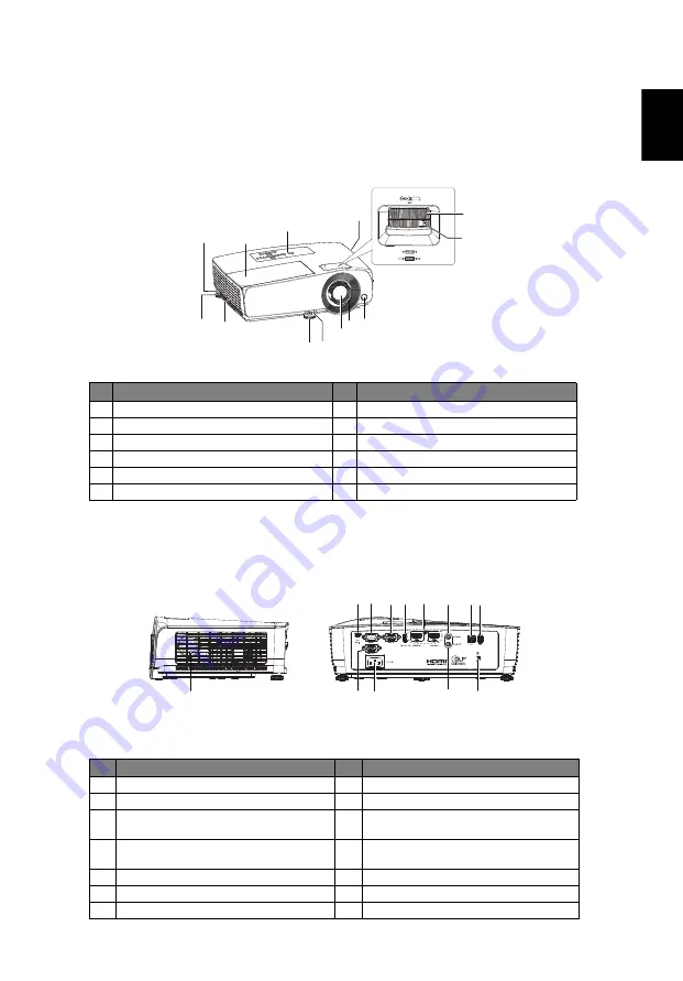
Projector Overview

Projector Outlook

Front / upper side

Rear / Left side

#

Description

#

Description

1

Control panel

7

Adjuster foot

2

Focus ring

8

Air outlet

3

Zoom ring

9

Security bar

4

Remote control receiver

10 Lamp cover

5

Projection lens 

11 Air inlet

6

Quick-release lever

#

Description

#

Description

1

Speaker

8

LAN (RJ45 Port for 10/100M Ethernet)

2

Mini USB connector

9

USB connector (5V/1.5A)

3

RS232 connector

10

Monitor loop-through output 

connector (VGA OUT)

4

PC analog signal/HDTV/component 

video input connector (VGA IN)

11

Power socket

5

USB connector (WIRELESS KIT)

12

Audio output connector

6

HDMI input connector

13

Kensington anti-theft lock slot

7

Audio input connector

9

10

1

4

5

6

7

7

8

2

2

3

11

1

11

13

2 3 4 5 6

7 8 9

10

12

<Left side>

<Rear side>

Summary of Contents for P1560Bi

Page 1: ...i BS 531K P1560BTi H6535Bi H6535BTi F1P1901 P1360WBi D721Ei EV W71Ki X1325WPi DX431Ei BS 331K P1360WBTi FWX1902 P1260Bi D711Ei EV X71Ki X1225Pi DX231Ei BS 131K P1260BTi FNX1903 P1160Bi D701Ei EV S71Ki X1125Pi DX131Ei BS 031K P1160BTi FSV1904 User s Guide ...

Page 2: ...lude the serial number model number and purchase information No part of this publication may be reproduced stored in a retrieval system or transmitted in any form or by any means electronically mechanically by photocopy recording or otherwise without the prior written permission of Acer Incorporated Model number _________________________________ Serial number __________________________________ Dat...

Page 3: ...e and located as close to the equipment operator as possible When you need to disconnect power to the equipment be sure to unplug the power cord from the electrical outlet Warnings Do not use this product near water Do not place this product on an unstable cart stand or table If the product falls it could be seriously damaged Slots and openings are provided for ventilation to ensure reliable opera...

Page 4: ...put rating This product s AC adapter is equipped with a three wire grounded plug The plug only fits in a grounded power outlet Make sure the power outlet is properly grounded before inserting the AC adapter plug Do not insert the plug into a non grounded power outlet Contact your electrician for details Warning The grounding pin is a safety feature Using a power outlet that is not properly grounde...

Page 5: ...n following environments Space that is poorly ventilated or confined At least 50cm clearance from walls and free flow of air around the projector is necessary Locations where temperatures may become excessively high such as inside of a car with all windows rolled up Locations where excessive humidity dust or cigarette smoke may contaminate optical components shortening the life span and darkening ...

Page 6: ...e sure to change the lamp when is showing warning message When changing the lamp please allow unit to cool down and follow all changing instructions Reset the Lamp Hour Reset function from the Onscreen display Management Lamp Settings menu after replacing the lamp module Do not attempt to disassemble this projector There are dangerous high voltages inside which may hurt you The only user serviceab...

Page 7: ...ction of the global environment please recycle For more information on the Waste from Electrical and Electronics Equipment WEEE regulations visit http www acer group com public Sustainability sustainability01 htm Mercury advisory For projectors or electronic products containing an LCD CRT monitor or display Lamp s inside this product contain mercury and must be recycled or disposed of according to...

Page 8: ...t may hurt your eyes To reduce the risk of fire or electric shock do not expose this product to rain or moisture Please do not open or disassemble the product as this may cause electric shock When changing the lamp please allow unit to cool down and follow all changing instructions This product will detect the life of the lamp itself Please be sure to change the lamp when it shows warning messages...

Page 9: ...Turning the Projector On Off 8 Turning on the Projector 8 Turning the projector off 9 Adjusting the Projected Image 10 Adjusting the Height of Projected Image 10 How to optimize image size and distance 11 How to get a preferred image size by adjusting distance and zoom 15 User Controls 19 Onscreen Display OSD Menus 19 Color 20 Image 22 Source 23 Setting 23 Management 25 Information 26 Acer LAN web...

Page 10: ...rk Setting 29 Crestron Setting optional 29 Appendices 30 Troubleshooting 30 LED Alarm Definition Listing 31 Replacing the Lamp 32 Ceiling Mount Installation 33 Specifications 36 Compatibility modes 38 Regulations and safety notices 40 ...

Page 11: ...e damage by adjusting color hue and brightness Versatile display modes Bright Presentation Standard Video User 3D enable optimum performance in any situation HDTV 480i p 576i p 720p 1080i p supported Lower power consumption and economy ECO mode extends lamp life Acer EcoProjeciton Technology delivers Intelligent power management approach and physical efficiency improvement Equipped with HDMI conne...

Page 12: ...ató Snelstartgids Hurtigstartveiledning Instrukcja szybkiego uruchomienia Guia de consulta rápida Краткое руководство Hızlı başlangıç kılavuzu Қысқаша нұсқаулық Tez İşəsalma Təlimatı Ghid de pornire rapidă Priročnik za hiter začetek Stručná príručka Pikaopas Snabbstartguide Ръководство за бърз старт Οδηγός γρήγορης εκκίνησης 快速使用指南 ڽ ବҵ ܶԧ クイックスタート ガイド คู มือการเริ มใช งานอย าง รวดเร ว ἁG ⴚG Vodič...

Page 13: ...er Description Description 1 Speaker 8 LAN RJ45 Port for 10 100M Ethernet 2 Mini USB connector 9 USB connector 5V 1 5A 3 RS232 connector 10 Monitor loop through output connector VGA OUT 4 PC analog signal HDTV component video input connector VGA IN 11 Power socket 5 USB connector WIRELESS KIT 12 Audio output connector 6 HDMI input connector 13 Kensington anti theft lock slot 7 Audio input connecto...

Page 14: ...ed by tilting the projector 30 degrees 8 Four directional select keys Use up down left right buttons to select items or make adjustments to your selection 9 ENTER Confirm your selection of items 10 MODE Press MODE to select the display mode from Bright Presentation Standard Video User 1 and User 2 11 BACK Go back to the previous menu or exit function 12 MENU Press MENU to launch the onscreen displ...

Page 15: ...lection 5 3D Only available for 3D input signal 6 BACK Go back to the previous menu or exit function STOP No function 7 RATIO To choose the desired aspect ratio 8 ZOOM Zooms in or out the projector display 9 PAGE For computer mode Use this button to select the next or previous page This function is available when USB Ctrl connector mini type B is connected to a computer via a USB cable Use this bu...

Page 16: ...ompensate for distortion caused by tilting the projector 30 degrees 16 Enter Confirm your selection of items Play Pause No function 17 MUTE To turn on off AV mute 18 MENU Press MENU to launch the onscreen display OSD menu or exit the OSD menu 19 MODE Press MODE to select the display mode from Bright Presentation Standard Video User 1 and User 2 20 Volume UP Down Increases or decreases the volume 2...

Page 17: ...pending on model definition Note USB cable needs powered extender if the length is over 5 m Description Description 1 Power cord 7 Audio cable Jack Jack 2 VGA cable 8 LAN cable 3 RS232 cable 9 USB cable for charging device 4 USB cable mini B to type A 10 USB flash drive 5 Component Video to VGA DSub adapter cable 11 Audio cable jack RCA 6 HDMI cable 12 Wireless dongle HDTV adapter 2 3 5 6 4 2 7 10...

Page 18: ...el or remote control and the Power indicator LED will flash green 3 Turn on your source computer notebook video player etc The projector will detect your source automatically If the screen displays No Signal please make sure the signal cables are securely connected If you connect to multiple sources at the same time use the Source button on the remote control or direct source key on the remote con...

Page 19: ...d off and the fan s will continue to operate to ensure that the system cools properly 3 Once the system has finished cooling the LED power indicator will stop blinking and turn solid orange to indicate standby mode 4 It is now safe to unplug the power cord Note Whenever the projector automatically shuts down and the LED lamp indicator turns solid red contact your local reseller or service center N...

Page 20: ...he height of image 1 Pull the quick release lever and lift the front of the projector Once the image is positioned where you want it release the quick release lever to lock the foot in position You may also screw the front adjuster foot to change the image height 2 Screw the rear adjuster feet to fine tune the horizontal angle Adjuster feet ...

Page 21: ... B W cm x H cm From base to top of image cm C 1 6 34 69 x 52 60 41 82 x 62 71 2 42 86 x 64 74 50 102 x 77 87 2 5 52 106 x 80 90 63 127 x 95 107 3 63 127 x 95 107 75 152 x 114 127 3 5 73 148 x 111 124 87 177 x 133 147 4 83 169 x 127 140 99 202 x 151 167 4 5 93 190 x 142 157 112 227 x 170 186 5 104 210 x 158 173 124 252 x 189 206 6 124 252 x 189 207 148 301 x 226 246 7 144 294 x 220 240 173 351 x 26...

Page 22: ...rom base to top of image cm C 1 6 34 70 x 52 61 41 83 x 63 72 2 43 87 x 65 74 51 103 x 78 88 2 5 53 108 x 81 91 63 129 x 96 107 3 63 129 x 96 107 76 154 x 115 127 3 5 74 150 x 112 124 88 179 x 134 147 4 84 171 x 128 141 100 204 x 153 167 4 5 94 192 x 144 158 113 229 x 172 187 5 105 213 x 159 174 125 254 x 191 207 6 125 255 x 191 208 150 304 x 228 247 7 146 297 x 222 241 174 354 x 266 287 8 167 339...

Page 23: ...ge cm C Diagonal inch B W cm x H cm From base to top of image cm C 1 3 33 71 x 45 52 40 86 x 53 61 2 50 108 x 68 75 60 130 x 81 89 2 5 62 134 x 84 92 75 161 x 101 110 3 75 161 x 100 109 89 192 x 120 130 3 5 87 187 x 117 126 104 224 x 140 150 4 99 213 x 133 143 119 255 x 160 171 4 5 111 239 x 150 160 133 287 x 179 191 5 123 265 x 166 177 148 318 x 199 212 6 148 318 x 199 211 177 381 x 238 252 7 172...

Page 24: ...ge cm C Diagonal inch B W cm x H cm From base to top of image cm C 1 2 33 74 x 42 50 40 89 x 50 59 2 55 121 x 68 78 66 146 x 82 93 2 5 68 150 x 85 96 82 182 x 102 115 3 81 180 x 101 113 98 217 x 122 136 3 5 94 209 x 118 131 114 253 x 142 157 4 108 239 x 134 149 130 289 x 162 179 4 5 121 268 x 151 166 147 324 x 182 200 5 134 297 x 167 184 163 360 x 202 222 6 161 356 x 200 219 195 431 x 243 264 7 18...

Page 25: ...stance m Top cm Diagonal inch A W cm x H cm Max zoom B Min zoom C From base to top of image D 40 81 x 61 1 6 1 9 70 50 102 x 76 2 0 2 4 86 60 122 x 91 2 4 2 9 103 70 142 x 107 2 8 3 4 119 80 163 x 122 3 2 3 9 135 90 183 x 137 3 6 4 3 151 100 203 x 152 4 0 4 8 168 120 244 x 183 4 8 5 8 200 150 305 x 229 6 1 7 3 249 200 406 x 305 8 1 9 7 330 250 508 x 381 10 2 12 2 411 300 610 x 457 12 2 14 6 493 Zo...

Page 26: ... cm x H cm Max zoom B Min zoom C From base to top of image D 40 81 x 61 1 6 1 9 70 50 102 x 76 2 0 2 4 86 60 122 x 91 2 4 2 8 102 70 142 x 107 2 8 3 3 118 80 163 x 122 3 2 3 8 134 90 183 x 137 3 6 4 3 151 100 203 x 152 4 0 4 8 167 120 244 x 183 4 8 5 7 199 150 305 x 229 6 0 7 2 248 200 406 x 305 8 0 9 6 328 250 508 x 381 10 1 12 0 409 300 610 x 457 12 1 14 5 490 Zoom Ratio 1 2x A C D B Desired Dis...

Page 27: ...A W cm x H cm Max zoom B Min zoom C From base to top of image D 40 86 x 54 1 3 1 6 61 50 108 x 67 1 7 2 0 75 60 129 x 81 2 0 2 4 89 70 151 x 94 2 3 2 8 103 80 172 x 108 2 7 3 2 117 90 194 x 121 3 0 3 6 131 100 215 x 135 3 4 4 0 145 120 258 x 162 4 0 4 9 173 150 323 x 202 5 1 6 1 215 200 431 x 269 6 8 8 2 285 250 538 x 337 8 5 10 2 355 300 646 x 404 10 2 12 3 424 Zoom Ratio 1 2x A C D B Desired Dis...

Page 28: ...h A W cm x H cm Max zoom B Min zoom C From base to top of image D 40 89 x 50 1 2 1 5 58 50 111 x 62 1 5 1 8 72 60 133 x 75 1 8 2 2 85 70 155 x 87 2 1 2 6 98 80 177 x 100 2 4 3 0 112 90 199 x 112 2 7 3 3 125 100 221 x 125 3 1 3 7 138 120 266 x 149 3 7 4 5 165 150 332 x 187 4 6 5 6 205 200 443 x 249 6 2 7 5 271 250 553 x 311 7 7 9 4 338 300 664 x 374 9 3 11 2 404 Zoom Ratio 1 2x A C B D Desired Dist...

Page 29: ...re setting Use the keys to select the desired item and adjust the settings by using the keys Select the next item to be adjusted in the submenu and adjust as described above Press BACK on the remote control the screen will go back to the previous menu or exit OSD Press MENU on the remote control to exit OSD directly The OSD menu will close and the projector will automatically save the new settings...

Page 30: ...elightShield is enabled LumiSense switches to Off Display Mode There are many factory presets optimized for various types of images Bright For brightness optimization Presentation For meeting presentation Standard For common environment Video For playing video in a bright environment EcoPro Dims the projector lamp to the very low status which will extend the lamp life to 20 000 hours User 1 User 2...

Page 31: ...e Use this function to choose CT1 CT2 CT3 mode Color Temperature Fine Tuning R Gain Adjusts the red gain for color temperature optimization G Gain Adjusts the green gain for color temperature optimization B Gain Adjusts the blue gain for color temperature optimization R Bias Adjusts the red bias for color temperature optimization G Bias Adjusts the green bias for color temperature optimization B B...

Page 32: ...s the ENTER button to enter 4 Corner Correction page Press the to select one of the four corners and then press the ENTER button Press the to adjust vertical position Press the to adjust horizontal position Press BACK to select other corners Repeat the same procedure with the positions for the corners Position Horizontal Centers the on screen image by moving it to the left or right Vertical Center...

Page 33: ...me You can project from behind a translucent screen with ceiling mounted projection Ceiling Front When you select this function the projector inverts the image for ceiling mounted projection Menu Settings Menu Display Time Choose the OSD menu display time Default is 20 seconds Select Manual to turn off main menu one direct key menu manually by user Menu Position Sets the On Screen Display OSD menu...

Page 34: ...tartup screen If you change the setting the changes will take effect when you exit the OSD menu USB 5V Standby Default is Off Choose On to supply 5V 1 5A pwoer while in standby mode VGA OUT Standby Default is Off Choose On to enable VGA OUT connection Firmware Upgrade Choose to upgrade firmware via USB drive or network ...

Page 35: ...R button and choose Yes to turn the lamp hour counter to 0 hours ECO Mode Choose On to dim the projector lamp which will lower power consumption extend the lamp life and reduce noise Choose Off to return normal mode Choose EcoPro to dim the projector lamp to the very low status which will extend the lamp life to 20 000 hours Security Settings Change Password To set or change password please follow...

Page 36: ...under standby status It is required to download WOL wake on LAN WOL tool or app for PC Mobile by users for this function DHCP On Projector will obtain an IP address automatically from your network Note Grey out when LAN isn t plugged in and LAN IP X X X X show 0 0 0 0 LAN Reset Reset LAN function Reset Press the ENTER button and choose Yes to return the parameters on all menus to the factory defau...

Page 37: ...ctor connects to your device through a LAN cable and set DHCP to off in Network Open browser and enter the Server IP address by 192 168 100 10 to find below homepage of acer LAN webpage management A password is needed to login in before using Default password of User is 0000 ...

Page 38: ...atus Change Password Projector Control Network Setting and Crestron System Status page is automatically selected after login Download EZCast Pro Installer for PC projection from Acer portal http www acer com projectors app Change Password Enduser can change the login password as wish ...

Page 39: ... value via this page Network Setting Enduser can set IP address as wish After change network configurations Network Setting on both webpage and projector will refresh automatically after press Apply Crestron Setting optional Enduser can change the settings for Crestron control system ...

Page 40: ...l source is turned on and connected For a computer connection ensure your notebook computer s external video port is turned on Refer to the computer manual If the image is out of focus While displaying the on screen menu adjust the focus ring The image size should not change if it does you are adjusting the zoom not the focus Check the projection lens to see if it needs cleaning If the image is fl...

Page 41: ... in normal operation Orage flashing Off Red Lamp is not lit up Orage flashing Off Orage flashing The remaining time of lamp life becomes 5 or lower Green Orange flashing Off Orange Fan 1 blower error the actual fan speed exceeds the desired speed Red Red Off Fan 2 air outlet error the actual fan speed exceeds the desired speed Red Orage flashing Off Fan 3 air inlet error the actual fan speed excee...

Page 42: ...or by pressing the Power button Allow the projector at least 45 minutes to cool down Disconnect the power cord 1 Remove the screw a and slide the lamp cover b for removal 2 Disconnect the lamp connector c 3 Remove the screw d that secure the lamp module Pull out the lamp module e by the handle f To replace the lamp module use a new lamp and reverse the above steps Warning To reduce the risk of per...

Page 43: ...unt please refer to the steps below 1 Drill four holes into a solid structurally sound part of the ceiling and secure the mount base 2 Choose the length combination based on actual environment CM 01S doesn t include Type 2 and Type 3 2 0 m m 1 3 m m 8 4 mm 130 mm 4 9 9 m m Type 1 Type 2 Type 3 ...

Page 44: ...atively for the larger size use the sliding extensions for more sup ports Note It is recommended that you keep a reasonable space between the bracket and the projector to allow for proper heat distribution 4 Connect the main body connector to the projector bracket illustration 1 and then screw up four screws illustration 2 Type 1 Type 2 Type 3 ...

Page 45: ...ate type of screw and washer for each model is listed in the table below 4 mm diameter screws are enclosed in the screw pack Screw Type B Washer Type Diameter mm Length mm Large Small 4 25 V V 360 SCREW SPEC M4 x 25 mm 66 50 107 5 92 6 172 44 116 1 125 8 216 41 7 238 94 84 23 5 ...

Page 46: ...720p 1080i 1080p EDTV 480p 576p SDTV 480i 576i Aspect ratio Auto 4 3 16 9 16 10 Displayable colors 1 07 billion colors Projection lens P1160Bi D701Ei EV S71Ki X1125Pi DX131Ei BS 031K P1160BTi FSV1904 P1260Bi D711Ei EV X71Ki X1225Pi DX231Ei BS 131K P1260BTi FNX1903 P1360WBi D721Ei EV W71Ki X1325WPi DX431Ei BS 331K P1360WBTi FWX1902 series F 2 42 2 62 f 22 25 79 mm 1 2X manual zoom and manual focus ...

Page 47: ...bs Dimensions W x D x H 332 mm X 244 mm X 108 mm 13 1 x 9 6 x 4 3 Digital Zoom 1 8X Power supply AC input 100 240 V auto switching power supply Power consumption Normal mode 270W 10 110VAC ECO mode 230W 10 110VAC EcoPro mode 166W 10 110VAC Standby mode 0 5W Network standby mode 3W Operating temperature 0ºC to 40ºC 32ºF to 104ºF Standard package contents AC power cord x1 Remote control x1 Battery x...

Page 48: ... 640x480 60 0 31 47 72 0 67 86 75 0 37 50 85 0 43 27 SVGA 800x600 60 0 37 88 72 0 48 08 75 0 46 88 85 0 56 67 XGA 1024x768 60 0 48 36 70 0 56 48 75 0 60 02 85 0 68 67 WXGA 1280x720 60 0 44 80 1280x768 60 0 47 78 1280x800 60 0 49 60 1360x768 60 0 47 71 WXGA 1440x900 60 0 55 90 SXGA 1152x864 75 0 67 50 1280x1024 60 0 63 98 75 0 79 98 1280x960 60 0 60 00 SXGA 1400x1050 60 0 65 32 WSXGA 1680x1050 60 0...

Page 49: ...76i 1080i interlaced signals are not supported Mode Signal Vertical frequency Hz Horizontal frequency kHz Analog Support Digital Support DTV Signal 480P 720x480p 59 9 31 50 576P 720x576p 50 0 31 60 720P 1280x720p 60 0 45 00 50 0 37 50 1080P 1920x1080p 24 0 27 00 60 0 67 50 50 0 56 30 ...

Page 50: ...e into an outlet on a circuit different from that to which the receiver is connected Consult the dealer or an experienced radio television technician for help Notice Shielded cables All connections to other computing devices must be made using shielded cables to maintain compliance with FCC regulations Notice Peripheral devices Only peripherals input output devices terminals printers etc certified...

Page 51: ...ooth modules Canada Low power license exempt radio communication devices RSS 247 a Common information Operation is subject to the following two conditions 1 This device may not cause interference and 2 This device must accept any interference including interference that may cause undesired operation of the device b Operation in 2 4 GHz band To prevent radio interference to the licensed service thi...

Page 52: ...nion harmonization legislations Directive 2014 53 EU on Radio Equipment RoHS Directive 2011 65 EU and ErP Directive 2009 125 EC The following harmonized standards and or other relevant standards have been applied Electromagnetic compatibility EN 55032 2015 AC 2016 Class B EN 55024 2010 A1 2015 EN 61000 3 2 2014 Class D EN 61000 3 3 2013 Radio frequency spectrum usage EN 301 489 1 V2 1 1 EN 301 489...

Page 53: ...use undesired operation The following local Manufacturer Importer is responsible for this declaration Product DLP Projector Model Number F1P1901 FWX1902 FNX1903 FSV1904 Machine Type P1560Bi D751Ei EV F71Ki X1525Pi DX531Ei BS 531K P1560BTi H6535Bi H6535BTi P1360WBi D721Ei EV W71Ki X1325WPi DX431Ei BS 331K P1360WBTi P1260Bi D711Ei EV X71Ki X1225Pi DX231Ei BS 131K P1260BTi P1160Bi D701Ei EV S71Ki X11...

Reviews: