background image

viii

)&&&ODVV%5DGLR)UHTXHQF\

,QWHUIHUHQFH6WDWHPHQW

Note:

This equipment has been tested and found to comply with the limits for
a Class B digital device, pursuant to Part 15 of FCC Rules.  These
limits are designed to provide reasonable protection against harmful
interference in a residential installation.  This equipment generates,
uses, and can radiate radio frequency energy and, if not installed and
used in accordance with the instructions, may cause harmful
interference to radio communications.  However, there is no guarantee
that interference will not occur in a particular installation.  If this
equipment does cause harmful interference to radio or television
reception, which can be determined by turning the equipment off and
on, the user is encouraged to try to correct the interference by one or
more of the following measures:

1.

Reorient or relocate the receiving antenna.

2.

Increase the separation between the equipment and receiver.

3.

Connect the equipment into an outlet on a circuit different from
that to which the receiver is connected.

4.

Consult the dealer or an experienced radio/television technician
for help.

Notice 1:

The changes or modifications not expressly approved by the party
responsible for compliance could void the user’s authority to operate
the equipment.

Notice 2:

Shielded interface cables, if any, must be used in order to comply with
the emission limits.

Summary of Contents for M9D

Page 1: ...0 6 VWHP User s Guide...

Page 2: ...y warranties merchantability or fitness for any particular purpose Any software described in this manual is sold or licensed as is Should the programs prove defective following their purchase the buye...

Page 3: ...a rug or other similar surface This product should never be placed near or over a radiator or heat register or in a built in installation unless proper ventilation is provided 6 This product should be...

Page 4: ...age points or other risks Refer all servicing to qualified service personnel 12 Unplug this product from the wall outlet and refer servicing to qualified service personnel under the following conditio...

Page 5: ...explode if not handled properly Do not recharge disassemble or dispose of it in fire Keep it away from children and dispose of any used battery promptly 15 Use only the proper type of power supply cor...

Page 6: ...ER TOUTE EXPOSITION AUX RAYONS VARO AVATTAESSA OLET ALTTIINA N KYM TT M LLE LASERS TEILYLLE L KATSO S TEESEEN VARNING OSYNLING LASERSTR LNING N R DENNA DEL R PPNAD BETRAKTA EJ STR LEN VARNING OSYNLING...

Page 7: ...en tilsvarende type anbefalt av apparatfabrikanten Brukte batterier kasseres i henhold til fabrikantens instruksjoner VARNING Explosionsfara vid felaktigt batteribyte Anv nd samma batterityp eller en...

Page 8: ...his equipment does cause harmful interference to radio or television reception which can be determined by turning the equipment off and on the user is encouraged to try to correct the interference by...

Page 9: ...It contains the system board layout jumper settings cache and memory configurations and information on other internal devices Chapter 2 CPU Board This chapter describes the dual processor CPU board It...

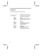
Page 10: ...Represent the actual keys that you have to press on the keyboard NOTE Gives bits and pieces of additional information related to the current topic CAUTION Gives precautionary measures to avoid possibl...

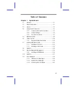
Page 11: ...ESD Precautions 1 9 1 6 Video Function 1 10 1 6 1 Supported Video Resolutions 1 10 1 7 Installing Expansion Cards 1 12 1 7 1 Installing a PCI Card 1 12 1 7 2 Installing an ISA Cards 1 13 1 8 ASM Pro...

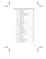
Page 12: ...m II Processor 2 10 2 4 1 Installing the Processor Heatsink and Fan 2 11 2 4 2 Installing the Processor Module 2 13 2 5 Uninstalling the Processor 2 15 2 5 1 Removing the Processor from the Slot 2 15...

Page 13: ...Pointing Device 3 7 3 2 15 Memory Parity Mode 3 7 3 2 16 Onboard USB 3 7 3 3 Product Information 3 8 3 3 1 Product Name 3 8 3 3 2 System S N 3 8 3 3 3 Main Board ID 3 9 3 3 4 Main Board S N 3 9 3 3 5...

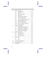
Page 14: ...6 10 Boot from Onboard SCSI Device 3 22 3 6 11 System Boot Drive 3 22 3 7 Advanced Configuration 3 23 3 7 1 Onboard Devices Configuration 3 24 3 7 2 PnP PCI System Configuration 3 30 3 7 3 Memory Cac...

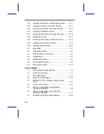
Page 15: ...k not defined 4 4 Quitting the SCSI Configuration Utility4 Error Bookmark not defined List of Figures 1 1 System Board Layout 1 4 1 2 System Board Jumper and Connector Locations 1 5 1 3 Installing a P...

Page 16: ...e CPU Board 2 20 4 1 Main Menu 4 3 4 2 Adapter Boot Order 4 4 4 3 Change Status on Next Boot 4 5 4 4 Utilities Menu 4 6 4 5 Adapter Setup Menu 4 7 4 6 Device Selections Menu 4 9 4 7 Device Setup Menu...

Page 17: ...xvii 3 2 Drive Control Settings 3 44 4 1 Settings for the Host Adapter and All Devices 4 2...

Reviews: