


Chapter 1
9
Indicators
The computer has several easy-to-read status indicators. The front panel indicators are visible even when the
computer cover is closed.
NOTE:
1.
Charging:
The light shows amber when the battery is charging. 2.
Fully charged:
The light shows
green when in AC mode.
Easy-Launch Buttons
Located beside the keyboard are application buttons. These buttons are called easy-launch buttons. They are:
WLAN, Internet, email, Bluetooth, Arcade and Acer Empowering Technology.
The mail and Web browser buttons are pre-set to email and Internet programs, but can be reset by users. To
set the Web browser, mail and programmable buttons, run the Acer Launch Manager.You can access the
Launch Manager by clicking on Start, All Programs, and then Launch Manager to start the application.
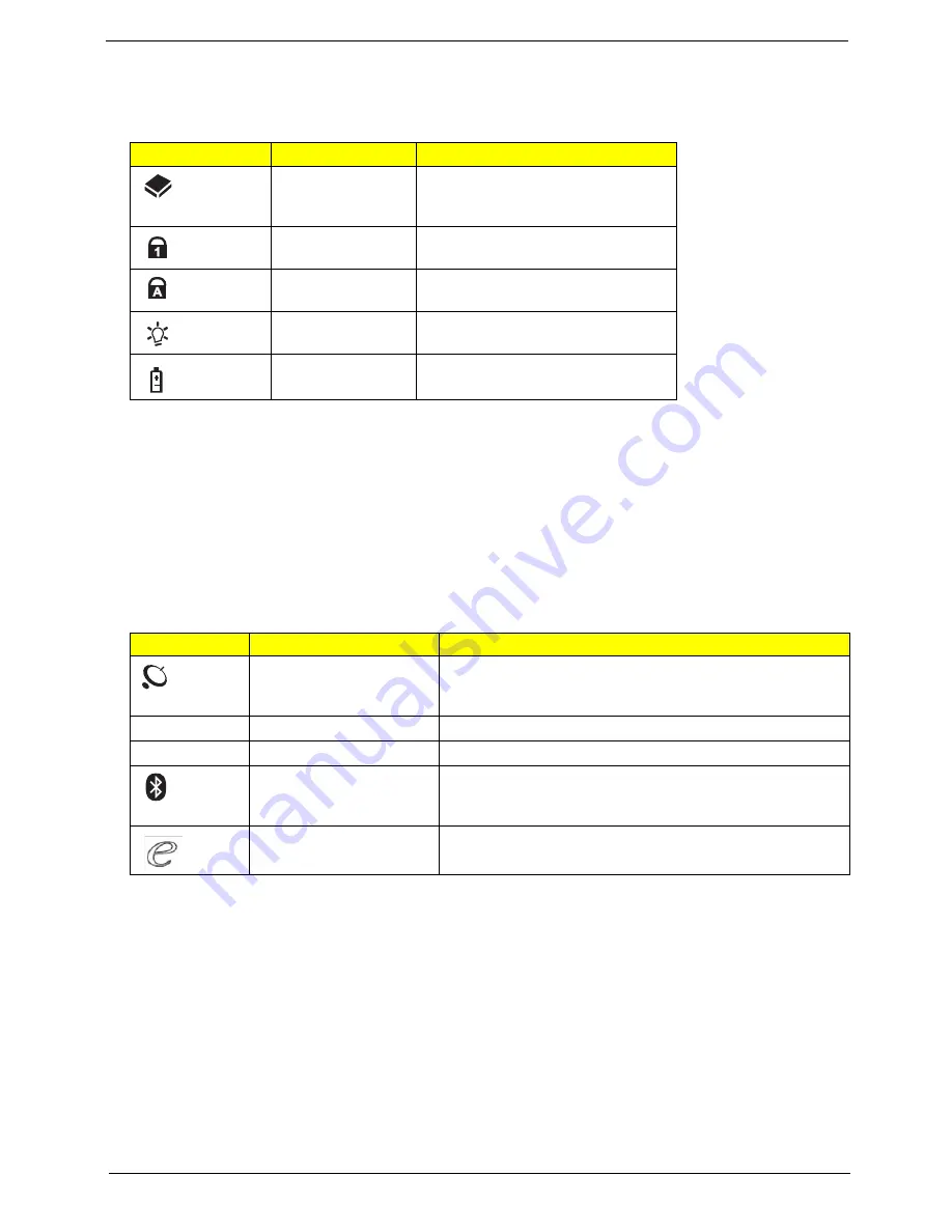
Icon
Function
Description
HDD
Indicates when the hard disk drive is
active.
Num Lock
Lights up when Num Lock is
activated.
Caps Lock
Lights up when Caps Lock is
activated.
Power
Indicates the computer's power
status.
Battery
Indicates the computer's battery
status.
Icon
Function
Description
Wireless communication
button/indicator
(manufacturing option)
Enables/disables the wireless function. Indicates the status
of wireless LAN communication.
VOL+
Volume up
Increases the sound volume.
VOL-
Volume down
Decreases the sound volume.
Bluetooth communication
button/indicator
(manufacturing option)
Enables/disables the Bluetooth function. Indicates the
status of Bluetooth communication.
Acer Empowering
Technology
Launch Acer Empowering Technology (user-
programmable)
Summary of Contents for LX.AUA0X.343
Page 6: ...VI ...
Page 9: ...IX Table of Contents Online Support Information 159 Index 161 ...
Page 10: ...X Table of Contents ...
Page 44: ...34 Chapter 1 ...
Page 58: ...46 Chapter 2 ...
Page 104: ...92 Chapter 3 13 Detach any adhesive tapes and any cable that is glued to the LCD panel ...
Page 108: ...96 Chapter 3 12 Remove the Web camera from the back cover ...
Page 122: ...110 Chapter 4 F5h Boot to Mini DOS F6h Clear Huge Segment F7h Boot to Full DOS Code Beeps ...
Page 129: ...Chapter 5 117 Top and Bottom View Jumper and Connector Locations Chapter 5 ...
Page 130: ...118 Chapter 5 ...
Page 134: ...122 Chapter 6 Aspire 5235 5535 Series Exploded Diagram ...
Page 147: ...Chapter 6 135 ...
Page 152: ...140 Appendix B ...
Page 154: ...142 Appendix C ...