background image


- 11 - 

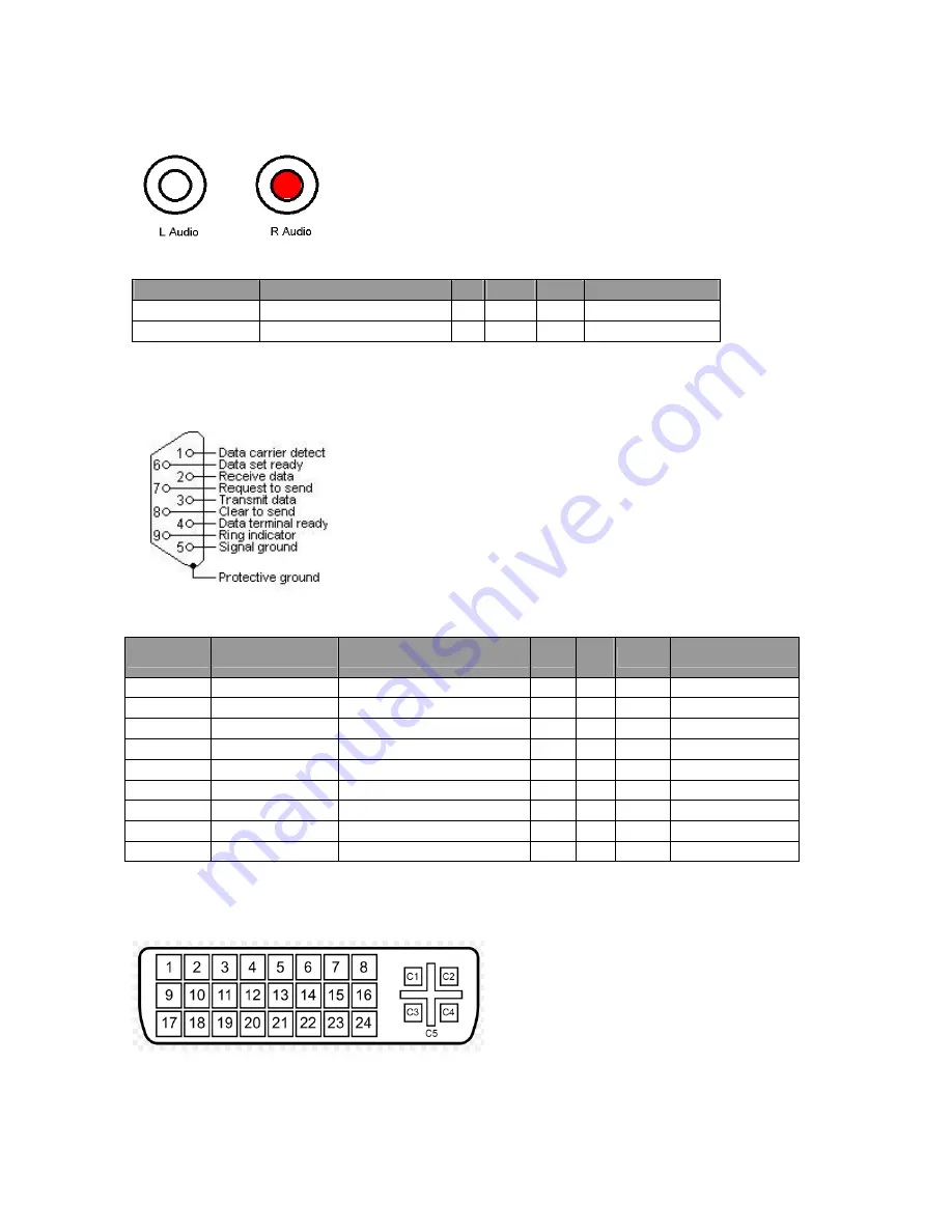
3.2.7  Audio Output (RCA-Jack ) 

(1) Pin definition 


(2) Signal Level: 

Signal 

Parameter 

Min  Type  Max 


Audio Out Right Amplitude  


Vrms 

Audio Out Left  Amplitude 


Vrms 


3.2.8  RS232 In/Output Port 
 

(1) Pin definition (D-Sub 9 Pin) 


(2) Signal Level: 
 

PIN 

Signal 

Parameter 

Min 

Typ

Max 


NC 


RX 

Amplitude (with sync) 

-25 


25 

Volt 

TX 

Amplitude 

-13.2   

13.2  Volt 

NC 


GND 


NC 


RTSZ 


CTSZ 


NC 


3.2.9  DVI In/Output Port 

(1) Pin definition (DVI 29 Pin) 


Summary of Contents for DV650C

Page 1: ...er DV650C Applicable for All Regions Version 001 Date 2011 10 21 Notice For RO to input specific Legal Requirement in specific NS regarding to responsibility and liability statements First Edition Oct 2011 Copyright Acer Corporation 2011 All Right Reserved ...

Page 2: ...5 Packing 21 4 Disassembly Assembly 22 4 1 Exploded View 22 4 2 Disassembly Assembly 23 5 Level 1 Cosmetic Appearance Alignment Service 31 5 1 Alignment procedure for function adjustment 31 5 2 Software Firmware Upgrade Process 36 5 3 EDID Upgrade Process 40 5 4 OSD Operation Guide 46 6 Level 2 Circuit Board and Standard Parts Replacement 48 6 1 Trouble Shooting Guide 48 6 2 Circuit Operation Theo...

Page 3: ...erform diagnostics tests troubleshoot problems and align the Acer product 1 1 Trademark The following terms are trademarks of Acer Inc Acer Importance Only trained service personnel who are familiar with this Acer Product shall perform service or maintenance to it Before performing any maintenance or service the engineer MUST read the Safety Note ...

Page 4: ...nd meets all government safety requirements 2 Ensure that other persons are safe while you are servicing the product DO NOT perform any action that may cause a hazard to the customer or make the product unsafe 3 Use proper safety devices to ensure your personal safety 4 Always use approved tools and test equipment for servicing 5 Never assume the product s power is disconnected from the mains powe...

Page 5: ...ion FHD 1920 x 1080 pixels Aspect Ratio 16 09 Brightness typ min 500 nits typ 425 nits min Contrast Ratio typ 5000 1 typ Response Time ms 8ms typ Pixel Pitch 0 744mm Frame Rate 60Hz Viewing Angle 178 degree H 178 degree V Light Life typ min 50 000 hrs min Panel Surface HCLR hard coating 3H Color gamut x NTSC 72 Panel Panel Bit 8 or 10 8bit FRC 1073 7M Platform Solution Scalar PW328B Voltage 100 V ...

Page 6: ...O Audio Output L R RCA O External Speaker Out L R O Audio Input L R O x2 HDMI In O DVI Input O DVI Output X VGA In O VGA Out O USB Touch to External PC X RS232 Input O RS232 Output O Component In YPbPr RCA O S Video In O Composite video In BNC O Composite video Out BNC O Display Port Input X Display Port Output X RJ45 Port Video Over Ethernet X IO RJ45 Port X Weight without packing with packing 53...

Page 7: ...manual electronic file O External Speaker X Stand X Optional Adaptor X Package Accessory Warranty card by region TBC Image Setting O Source Volume Control O VGA Daisy Chain O DVI Daisy Chain X RS232 Control Daisy Chain O ID Setting O Sharpness Enhancement O Proof of Image Retention O DDC CI X Diming Control DCR O Picture in Picture PIP O De Interlacing Comb Filter O 10 Bit color processing O Build...

Page 8: ...olts peak to peak Amplitude video 0 7 Volts peak to peak Amplitude sync 0 3 Volts peak to peak CVBS Luminance Impedance 75 ohm 3 2 2 S Video Input 1 Pin definition Mini Din 4 pin Mini Din Connector 2 Signal Level PIN Signal Parameter Min Type Max 1 GND 2 GND Amplitude total video sync 1 Volts peak to peak Amplitude video 0 7 Volts peak to peak Amplitude sync 0 3 Volts peak to peak 3 CVBS Luminance...

Page 9: ...o peak 3 Black pedestal 0 Volts RDATA GDATA BDATA Pixel Clock 170 M Hz Impedance 75 Ohm Amplitude 1 Volts peak to peak Video amplitude 0 7 Volts peak to peak Sync amplitude 0 3 Volts peak to peak Black pedestal 0 Volts 2 GDATA_SOG Pixel Clock 170 M Hz Impedance 1 K ohm Amplitude low level 0 0 5 volt Amplitude high level 2 5 5 Volt 13 HDATA Frequency 31 99 K Hz Impedance 1 K ohm Amplitude low level...

Page 10: ...DATA Share with Pb Impedance 75 ohm 3 2 5 Audio Input RCAx2 1 Pin definition 2 Signal Level N A PIN Signal Parameter Mi n Typ e Ma x Amplitude 0 5 2 VRMS 1 L Audio Impedance 10 KΩ Amplitude 0 5 2 VRMS 2 R Audio Impedance 10 KΩ 3 2 6 Audio Line Input Phone Jack φ3 5mm 1 Pin definition 2 Signal Level PIN Signal Parameter Mi n Typ e Ma x Amplitude 0 5 2 VRMS 1 Audio In Right Impedance 10 KΩ 2 NC 3 NC...

Page 11: ...mplitude 2 Vrms Audio Out Left Amplitude 2 Vrms 3 2 8 RS232 In Output Port 1 Pin definition D Sub 9 Pin 2 Signal Level PIN Signal Parameter Min Typ e Max 1 NC 2 RX Amplitude with sync 25 25 Volt 3 TX Amplitude 13 2 13 2 Volt 4 NC 5 GND 6 NC 7 RTSZ 8 CTSZ 9 NC 3 2 9 DVI In Output Port 1 Pin definition DVI 29 Pin ...

Page 12: ... Link 1 Pin 11 TMDS Data 1 3 shield Pin 12 NA NA Pin 13 NA NA Pin 14 5 V Power for monitor when in standby Pin 15 Ground Return for pin 14 and analog sync Pin 16 Hot plug detect Pin 17 TMDS data 0 Digital blue Link 1 and digital sync Pin 18 TMDS data 0 Digital blue Link 1 and digital sync Pin 19 TMDS data 0 5 shield Pin 20 NA NA Pin 21 NA NA Pin 22 TMDS clock shield Pin 23 TMDS clock Digital clock...

Page 13: ...S Data2 Pin 4 TMDS Data1 Pin 5 TMDS Data1 Shield Pin 6 TMDS Data1 Pin 7 TMDS Data0 Pin 8 TMDS Data0 Shield Pin 9 TMDS Data0 Pin 10 TMDS Clock Pin 11 TMDS Clock Shield Pin 12 TMDS Clock Pin 13 CEC Pin 14 Reserved N C on device Pin 15 SCL Pin 16 SDA Pin 17 DDC CEC Ground Pin 18 5 V Power max 50 mA Pin 19 Hot Plug Detect ...

Page 14: ...lation Efficiency 80 typical measuring at 115Vac and full load 3 4 Software Specification 3 4 1 Compliant Timing Remark for 800x480 72Hz 60 80 Hz Positive Hsync Polarity Negative Vsync Polarity Positive Data Enable Polarity Pixel Clock 36 8 MHz Vertical Freq 72 1 Hz Vsync 6 lines Vertical Front Porch 20 lines Vertical Back Porch 54 Lines Vertical Total 560 lines Horizontal Freq 40 4 kHz Hsync 48 p...

Page 15: ... 15 3 4 2 OSD Table Generic for Version 2 4 1 ...

Page 16: ...Lock Functon Consolidated Standard Hot key Button lock L R for 5s Menu lock U D for 5s Power lock Menu R for 5s IR Lock Menu L for 5s RS232 U R FACTORY MODE L PWD under POWER off mode for 5s ENGINEER MODE R PWD under POWER off mode for 5s ...

Page 17: ... 17 3 4 4 Remote Control Function and Key Code Definition IR Remote Lock Functon OSD Lock Down for 3 Seconds then press Enter OSD Unlock Down for 3 Seconds then press Enter ...

Page 18: ... ID Product Code must be four characters Monitor Name can be none or maximum 13 characters S N Acer requests to implement 22 digit S N 3 4 8 RS 232 Command Table Len ID Cmd Command Value Range Get Function Type Code ASCII Code Hex Three ASCII bytes Comments 8 g B1 000 STANDARD 001 VIVID 002 CINEMA Picture mode 003 USER Contrast 8 g 61 000 100 Brightness 8 g 62 000 100 Color 8 g B2 000 100 Tint 8 g...

Page 19: ...YPbPr 002 DVI PIP Sub Input 003 HDMI 8 g BD 000 Small 001 Middle PIP Size 002 Large 8 g 6A 000 VGA 001 HDMI1 003 CVBS1 004 YPbPr 005 S Video Video Source 006 DVI Clock frequency 8 g C0 000 32 Phase 8 g C1 000 32 H Position 8 g C2 000 100 V Position 8 g C3 000 100 8 g C4 000 OFF Ambient Light Sensor 001 ON 8 g C5 000 OFF Blue Screen 001 ON 8 g C6 000 OFF Auto Detect 001 ON 8 g CE 000 OFF Touch Feat...

Page 20: ...00 OFF Image retention 001 ON 8 g DA 000 OFF Auto adjustment 001 ON 8 g DB 000 OFF DDC CI 001 ON FW Version 16 g DC PS5550 p xx ASCII the return value will be different for different model 8 g 5D 000 OFF OSD Info Box 001 ON 8 g 74 000 STBY Power 001 ON 8 g 68 000 Disable Lock 001 Enable Remote Control 002 Pass through 8 g 69 000 Disable Lock Key Pad function 001 Enable 8 g 73 000 Disable Lock Menu...

Page 21: ... 21 3 5 Packing ...

Page 22: ... 22 4 Disassembly Assembly 4 1 Exploded View ...

Page 23: ...are the area for material flow according to the actual condition plan the disassemble layout 4 Prepare the implement equipments materials as bellow 1 Working table 2 Electric screw driver 2 3 Manual screw driver 1 4 Hex screw driver 5 Glove 6 Cleaning cloth 7 ESD protection Item picture Operation Tool Notes 1 Disassemble the shielding cover 21 M4 screws Electric screw drive 2 2 Disassemble the Upp...

Page 24: ... 10 M4 screws 2 Take off Inverter LVDS wires from PWR board color EG board Electric screw drive 2 4 Disassemble the front bezel 24 M4 screws Electric screw drive 2 5 Disassemble Handle from back cover x4 8 M8 screws Electric screw drive 2 ...

Page 25: ...rive 2 7 1 Tear off five acetic tapes 2 Disassemble the Lift Inverter single wire 3 Disassemble the Right Inverter dual wire 4 Disassemble the LVDSwire Electric screw drive 2 8 1 Tear off an acetic tape 2 Disassemble the IR Trans BD Keypad BD 5 M3 screws Electric screw drive 2 ...

Page 26: ...f speaker module from PCBA module 4 M3 screws 2 Take off Fans from PCBA module 4 M4 screws 3 Take off the LVDS Audio Power and Color wires Electric screw drive 2 11 1 Take off AC switch BD from PCBA module 4 M3 screws 2 Take off Color BD from PCBA module 4 M3 screws Electric screw drive 2 1 1 2 2 ...

Page 27: ...e Audio BD 4 M3 screws 5 T3 screws Electric screw drive 2 13 2 Disassemble Main BD 6 M3 screws 1 T3 screws 10 Hex screws Electric screw drive 2 Hex screw drive 14 2 Disassemble Power BD 12 M3 screws Electric screw drive 2 ...

Page 28: ... R and Panel II Connected two inverter wires to panel II Added 5 acetate tapes to fix wires B 1 Combine rear cover L R and Panel 2 Combine handle and rear cover L R C Combine Front Bezel and Panel Inverter 1 1 Rear cover R 2 3 4 5 Inverter 2 Rear cover L ...

Page 29: ...Lens 2 To combine Bezel and IR module E Combine transfer BD Keypad BD and button to rear cover top F Combine speakers to speaker holders for 2 sets G To combine Power BD AD BD Audio BD Color engine AC switch and AC socket to chassis ...

Page 30: ...ules and Chassis module I 1 To combine chassis module and Panel module J To combine SHD to display module K 1 Combine Top Cover to display module 2 Connect keypad IR Transfer FFC wires 3 Add an AL tape Chassis Module SHD TOP COVER AL TAPE ...

Page 31: ...htness 50 contrast 50 when HDMI PC mode input User OSD brightness 50 contrast 55 when YPbPr input User OSD brightness 50 contrast 55 when HDMI Video mode input User OSD brightness 50 contrast 53 when CVBS input User OSD brightness 50 contrast 53 when S Video input Table 1 1 Color temp item factory OSD CVBS1 CVBS2 S VIDEO VGA DVI HDMI Color temperature 12000 K x 0 270 0 01 y 0 281 0 01 Table 1 2 Co...

Page 32: ...K Red drive 127 127 Green drive 127 127 Blue drive 127 127 Red offset 127 127 Green offset 127 127 Blue offset 127 127 Color temp item factory OSD CVBS1 CVBS2 S VIDEO VGA DVI HDMI Color temperature 6500 K 6500 K Red drive 127 127 Green drive 127 127 Blue drive 127 127 Red offset 127 127 Green offset 127 127 Blue offset 127 127 Table 3 limit value of RGB drive offset Color temp item factory OSD CVB...

Page 33: ... 110 140 110 140 PC Auto Timing Check 1 Timing list Resolution Horizontal Frequency KHz Vertical Frequency Hz Dot Clock Frequency MHz Remark 800 600 37 879 60 317 40 0 VESA 2 Setup input timing VESA 800x600 37 878K 60 3Hz using Chroma 22293 pattern No 1 the same as below to do Auto Adjust PC RGB ADC Calibration 1 Setup input timing VESA 800x600 37 9K 60Hz 16 Grays pattern to DSUB connector 2 Setup...

Page 34: ... coordinate to meet the table1 spec 10 Do step 1 to 9 to get the drive offset values of 12000 KColor Temperature 11 Do step 1 to 9 to get the drive offset values of 9300 KColor Temperature 12 Do step 1 to 9 to get the drive offset values of 6500 KColor Temperature Video Color adjustment 1 Input source set the CVBS1 CVBS2 S Video input 2 Set the picture mode to standard mode at user OSD 3 Setup inp...

Page 35: ...ixels displaying white From more information see Fig 7 1 When VDDB 24V IDDB 14 6A LWH Lon1 Where Lon1 is the luminance with all pixels displaying white at center 1 location just for reference no spec 5 Position the CA 210 at the locations indicated on the grid there are 5 points see Fig 7 1 Measure and Record the values when the GRID is OFF 6 Panel spec brightness minimum 425 nits typical 500 nits...

Page 36: ... RS232 cable connect between PC Notebook with tool board RS232 is RXD and TXD interlaced line Personal computer or Notebook Download tool program Pixelworks ImageProcessor SDK FlashUpgrader 5 2 1 2 Firmware files 5 2 2 Procedure 1 Open firmware program files 2 Choose FlashUpgrar exe files ...

Page 37: ...e The Connection COM Port in accordance with user by oneself PC NB choose The Notify On Completion in accordance with user by oneself PC NB choose 4 The RS232 Download cable insert RS232 INPUT pin 5 Press Flash key of Pixelworks ImageProcess or SDK FlashUpgrader ...

Page 38: ... 38 6 The key change to cancel after Press Flash key 7 The Power code cable insert 8 The pixelworks ImageProcess or SDK FlashUpgrader program download start ...

Page 39: ... 39 9 The firmware download will finish after about 5 minutes 10 Please press 確定 Download program finish 11 Please pull out Power code RS232 Download cable ...

Page 40: ... 3 EDID Upgrade Process 5 3 1 Configuration and procedure 1 Install CustomerTool_V1 2 in PC or NB 2 Press Y to install DriverLINX Port I O Driver 3 Follow the installed steps and press NEXT to Install Driver ...

Page 41: ...tart computer 5 Prepare the download equipment Use USB cable connect to PC and Tool Board Use VGA cable connect to Tool Board and Display Display PC or NB VGA cable for EDID writing need to be removed pin5 to disable EDID write protect ...

Page 42: ... 42 6 Plug power cord into Display and run DebugTool_V6 2 file 7 Update EDID select EDID Update Communication select USB ISP Type select Serial Flash OK Fail For EDID Updated ...

Page 43: ... 43 8 EDID upload VGA EDID length select and then press to select EDID file and then press to write EDID into display 128B for VGA To write EDID Open EDID file ...

Page 44: ... 44 Power off status and LED Red 9 EDID upload DVI EDID length select and then press to select EDID file and then press to write EDID into display 128B for DVI Open EDID file To write EDID ...

Page 45: ...d 10 EDID upload HDMI EDID length select and then press to select EDID file and then press to write EDID into display 11 When EDID is uploaded and finished successfully it will shows as below 256B for VGA Open EDID file To write EDID ...

Page 46: ... 46 5 4 OSD Operation Guide ...

Page 47: ... 47 ...

Page 48: ...ack light and power board Yes No Input signal display No OSD image ok Yes No Check J24 LVDS cable connection Check input cable 1 Check IR Lign wire cable Audio wire cable or Sensor wire cable to check which one is short to cause this fail 2 Check keypad board NG or OK No Keypad LED ON 1 Check wire cable connection between main board and keypad 2 Check VCC 5V in No Yes Yes Audio ok Function ok No 1...

Page 49: ...input No CVBS1 input No CVBS2 input 1 Check J10 pin14 and R412 2 Check U18 U20 R124 R134 1 Check P5V P2V5 P3V3 P1V8 2 Check J25 PWRBD_ON and LCD_BRT_CTRL Signal 3 Check P5V P2V5 P3V3 P1V8 4 Check J25 PWRBD_ON and LCD_BRT_CTRL Signal 1 Check J8 soldering 2 Check U8 U10 U20 R124 R134 1 Check J31 soldering 2 Check L2 L3 R1 R3 1 Check J31 soldering 2 Check L1 R2 R483 1 Check J30 soldering 2 Check L4 R...

Page 50: ...ard U1 output waveform 1K Hz sinewave Check mute pin AUDIO_VOL_ON is high or low Yes Yes To measure audio board U1 output waveform Yes Check GPIO control pin R277 R278 status Check GPIO control pin R492 status Check audio board U1 soldering or change another chip No No No Check audio board U6 Power AMP soldering or change another chip No Yes ...

Page 51: ...r button operation is normal Yes Keypad LED is ON Yes Check POWER ON control pin is high No Check GPIO status Yes Check LCD12V and LVDS power sequence No Check GPIO status Check power is correctly Check input source and path is ready Yes ...

Page 52: ...4 is mounted Check U28 soldering or to change a new chip CVBS or S video repeat output no signal Check U1 or U2 operation normal VGA repeat output no signal Check U5 operation normal DVI or HDMI picture display abnormal Check C96 is mounted N C is normal IR function fail Check cable or change another IR board Detect ambient light function fail Check cable or change another IR board Scheduling func...

Page 53: ...tput audio interface support HDMI S Video CVBS Line in YPbPr audio source We can use IR RS232 or keypad to control function PW328B is a image processor it can support digital and analog input source output signal send to LCD Panel module by LVDS interface By the function separate all system into 6 PCBA Include main board audio board Keypad board IR board ambient light sensor board dimmer sensor bo...

Page 54: ...INGAL4 16 GND SIGNAL GND 17 TXO3 LVDS2 SINGAL3 18 TXO3 LVDS1 SINGAL3 19 GND SIGNAL GND 20 TXE3 LVDS2 SINGAL3 21 TXE3 LVDS2 SINGAL3 22 TXE4 LVDS2 SINGAL4 23 TXE4 LVDS2 SINGAL4 24 GND SIGNAL GND 25 TXO0 LVDS1 SIGNAL0 26 TXO2 LVDS1 SIGNAL2 27 TXO1 LVDS1 SIGNAL1 28 TXO1 LVDS1 SIGNAL1 29 TXE0 LVDS2 SINGAL0 30 TXE0 LVDS2 SINGAL0 31 GND SIGNAL GND 32 TXE1 LVDS2 SINGAL1 33 TXE1 LVDS2 SINGAL1 34 GND SIGNAL...

Page 55: ...WER 12V 10 12VIN POWER 12V 11 GND POWER GROUND 12 GND POWER GROUND d Keypad board link with main board connector J11 pin define pin Net Function Description pin Net Function Description 1 KEY0 KEY FUNCTION 0 2 KEY1 KEY FUNCTION 1 3 GND GROUND 4 LED2_R RED COLOR LED ON 5 LED2_G GREEN COLOR LED ON 6 KEY2 KEY FUNCTION 2 7 KEY3 KEY FUNCTION 3 8 KEY4 KEY FUNCTION 4 9 KEY5 KEY FUNCTION 5 10 KEY6 KEY FUN...

Page 56: ...328B delivers rich features and the performance you expect from Pixelworks at globally competitive price points Features include full 10 bit data processing high quality motion adaptive deinterlacing up to with enhanced low angle processing frame rate conversion Picture in Picture PIP Picture off Picture POP and high quality scaling In addition the chip offers programmable PixelBoost technology ad...

Page 57: ... sources coming on the market including DVDs Set Top Boxes STBs game consoles PCs camcorders and digital still cameras The SiI9185Aswitch is a fully compliant HDMI device that provides a simple low cost method of retransmitting protected digitalaudio and video giving consumers a truly alldigital experience Built in backward compatibility withDVI 1 0 allows HDMI systems to connect to any DVI1 0 sou...

Page 58: ...e deep color video up to 12 bit 1080p 60Hz Backward compatibility with DVI 1 0 allows HDMI systems to connect to existing DVI 1 0 hosts such as HD set top boxes and PCs The specialized audio and video processing contained in the receiver can add HDMI capability to earlier generation consumer electronics Efficient color space conversion receives RGB video data and outputs either standard definition...

Page 59: ...ed TMDS signals as well as increasing capacitance to the DDC channel Each TMDS141 contains four TMDS repeaters to transmit digital content with signaling rates of up to 1 65 Gbps and an I2C repeater to link extended display identification data EDID reading and high bandwidth digital content protection HDCP key exchange under I2C standard mode operations TMDS141 Functional Block Diagram ...

Page 60: ...lications The ADA4417 3 operates on a single 3 3 V to 5 V supply It is well suited for applications where power consumption is critical A disable feature allows for further power conservation by reducing the supply current to 10 µA typical when the device is not in use With rail to rail output it can be efficiently used on a 3 3 V supply while providing the user with a 2 V p p output The buffers c...

Page 61: ...e voltages or output a 0V level for video applications The 195 MHz large signal 3dB bandwidth at a fixed gain of 2 as well as the 740 V us slew rate make this amplifier ideal for high resolution professional and consumer video applications The amplifier also has a wide input common mode voltage range that extends from 1 8V below ground to 1 2 V below the positive rail at 5V supply ADA4859 Connecti...

Page 62: ...The high efficiency of the TPA3009D2 eliminates the need for external heatsinks when playing music Stereo speaker volume is controlled with a dc voltage applied to the volume control terminal offering a range of gain from 40 dB to 36 dB Line outputs for driving external headphone amplifier inputs are also dc voltage controlled with a range of gain from 56 dB to 20 dB TPA3009D Functional Block Diag...

Page 63: ...S HEX 4 40 NI MACHINE 5 0 5 AD BD 10 5 8F 4A726 6R0 SCRW MACH BIND M4 6L B NI MACHINE 10 1 0 BEZEL 23 RC L R T 23 CHASSIS 8 2 6 8F 4A756 100 SCRW M BIND M4 10L B NI NY MACHINE 10 1 0 SHD 21 2 7 8F AA322 6R0 SCRW TAP PH M2 6L B ZN TAPPING 2 0 5 BNC 1 1 8 8F PA724 8R0 SCRW TAP PH M3 8L B NI TAPPING 5 0 5 AUDIO BD 5 2 9 8F PG226 100 SCRW TAP PAN W FL M4 10L ZN TAPING 5 1 0 SPK 4 2 10 8F VG334 6R0 SCR...

Page 64: ... 64 Appendix 2 Physical Dimension Front View and Side view Fig 1 Physical Dimension Front View and Side view ...

Page 65: ... 65 Appendix 3 I F Board ...

Page 66: ... 66 ...

Page 67: ... 67 ...

Page 68: ... 68 ...

Page 69: ... 69 ...

Page 70: ... 70 ...

Page 71: ... 71 ...

Reviews: