Acer Chromebook C852 Lifecycle Extension Manual Download Page 17

Disassembly Procedures

1-15

7. Release the I/O bracket from the USB port slot and guide pins (G) on the top 

assembly. Then remove the I/O bracket (H) (

Figure 1-19

).

Figure 1-19. USB Board Removal

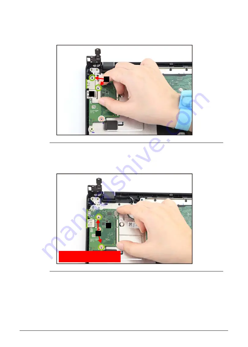
8. Release the USB board from the USB ports slots and guide pins (I) on the top 

assembly. Then remove the USB board (J) (

Figure 1-20

).

Figure 1-20. USB Board Removal

H

G

WEEE Annex VII Component: 

USB Board

J

I

Summary of Contents for Chromebook C852

Page 1: ...Acer Chromebook C852 C852T LIFECYCLE EXTENSION GUIDE ...

Page 2: ...i Self Repair 1 1 Disassembly Procedures 1 2 Troubleshooting 1 32 FRU Field Replaceable Unit List 1 36 Exploded Diagrams 1 37 Check for updates yourself 1 40 Factory reset your Chromebook 1 41 ...

Page 3: ...TE For replacement parts always use only Acer certified components in order to safeguard quality optimum system performance stability and reliability of the product NOTE NOTE Any damage to the product that occur during self repair or which has occurred as a result of a careless or unsuccessful self repair attempt is not covered by the standard product warranty Software Recovery 0 This product has ...

Page 4: ...wrist grounding strap or by periodically touching an unpainted metal surface at the same time as touching a connector on the back of the computer Take off any metal objects on your arms or fingers such as bracelets rings or watches and make sure your hands are completely dry Even if your unit is unplugged there may still be some remaining electric charge If a component does not come out easily do ...

Page 5: ...Disassembly Procedures 1 3 WEEE Annex VII Component 0 These components are classified as requiring selective treatment Battery pack Touchpad module USB board Mainboard LCD panel ...

Page 6: ...Place the system on a stable work surface 2 Remove the power adapter from the USB Type C port A or B as shown in Figure 1 1 or Figure 1 2 3 Remove all cables from system Figure 1 1 AC Adapter Outlet 4 Remove the microSD card from the microSD card slot C Figure 1 2 Figure 1 2 AC Adapter Outlet and MicroSD Card Removal A C B ...

Page 7: ...Disassembly Procedures 1 5 NOTE NOTE Make sure the system is completely powered off ...

Page 8: ...emoval 0 1 Remove eleven 11 screws from the base cover Figure 1 3 Figure 1 3 Base Cover Removal 2 Carefully pry up the base cover starting from the upper right side as shown in Figure 1 4 to release the latches Figure 1 4 Base Cover Removal ...

Page 9: ...Disassembly Procedures 1 7 3 Continue releasing the remaining latches Then remove the base cover Figure 1 5 Figure 1 5 Base Cover Removal ...

Page 10: ...nd the battery pack A on the top assembly Figure 1 6 2 Detach the acetate tape B securing the battery cable to the mainboard connector Figure 1 6 Figure 1 6 Battery Pack Removal 3 Disconnect the battery cable from the mainboard connector C Figure 1 7 Figure 1 7 Battery Pack Removal A B C ...

Page 11: ...sembly Procedures 1 9 4 Remove the battery pack from the top assembly Figure 1 8 Figure 1 8 Battery Pack Removal IMPORTANT Follow local regulations for battery disposal WEEE Annex VII Component Battery Pack ...

Page 12: ...he touchpad FFC Then disconnect the keyboard FPC from the mainboard connector B Figure 1 9 Figure 1 9 Touchpad Module Removal 2 Disconnect the touchpad FFC from the touchpad module connector C and the mainboard connector D Then remove the touchpad FFC from the top assembly Figure 1 10 Figure 1 10 Touchpad Module Removal B A D C ...

Page 13: ...adhesive tape E securing the keyboard FPC Figure 1 11 Figure 1 11 Touchpad Module Removal 4 Slightly lift the mylar Then detach the conductive tape F from the touchpad module and top assembly Figure 1 12 Figure 1 12 Touchpad Module Removal E F ...

Page 14: ...g the screwdriver push the guide pins G firmly to release them from the top assembly Figure 1 14 7 Slide the touchpad module slightly to disengage it from the bottom latches H and then remove the touchpad module I from the top assembly Figure 1 14 Figure 1 14 Touchpad Module Removal I H H WEEE Annex VII Component Touchpad Module G G G ...

Page 15: ...ard Removal 0 Prerequisite Battery Pack Removal 1 Remove three 3 screws A securing the right LCD hinge Figure 1 15 Figure 1 15 USB Board Removal 2 Lift the top assembly until it is fully open Figure 1 16 Figure 1 16 USB Board Removal A ...

Page 16: ...oard FFC from the mainboard connector B and the USB board connector C Then remove the 20 pin USB board FFC Figure 1 18 5 Disconnect the 50 pin USB board FFC from the mainboard connector D and the USB board connector E Then remove the 50 pin USB board FFC Figure 1 18 6 Remove two 2 screws F securing the USB board and I O bracket Figure 1 18 Figure 1 18 USB Board Removal C B E D F ...

Page 17: ... G on the top assembly Then remove the I O bracket H Figure 1 19 Figure 1 19 USB Board Removal 8 Release the USB board from the USB ports slots and guide pins I on the top assembly Then remove the USB board J Figure 1 20 Figure 1 20 USB Board Removal H G WEEE Annex VII Component USB Board J I ...

Page 18: ...oard Removal 0 Prerequisite Battery Pack Removal 1 Remove three 3 screws A securing the left LCD hinge Figure 1 21 Figure 1 21 Mainboard Removal 2 Lift the top assembly until it is fully open Figure 1 22 Figure 1 22 Mainboard Removal A ...

Page 19: ...ure 1 24 6 Disconnect the 50 pin USB board FFC from the mainboard connector D Figure 1 24 7 Disconnect the keyboard FPC from the mainboard connector E Figure 1 24 8 Disconnect the touchpad FFC from the mainboard connector F Figure 1 24 9 Disconnect the speaker cable from the mainboard connector G Figure 1 24 10 Disconnect the eDP cable from the mainboard connector H Figure 1 24 CAUTION Make sure a...

Page 20: ...ecuring the mainboard and I O bracket Figure 1 24 Figure 1 24 Mainboard Removal 12 Release the I O bracket from the USB port slot and guide pins J on the top assembly Then remove the I O bracket K Figure 1 25 Figure 1 25 Mainboard Removal F E D C B G H I K J ...

Page 21: ...ssembly Then remove the mainboard M Figure 1 26 Figure 1 26 Mainboard Removal Figure 1 27 Mainboard IMPORTANT Circuit boards 10 cm have been highlighted with a yellow rectangle as shown in Figure 1 27 Remove the circuit board and follow local regulations for disposal WEEE Annex VII Component Mainboard L M L ...

Page 22: ...m the mainboard connector A Figure 1 28 2 Remove one 1 screw securing the keyboard in place Figure 1 28 Figure 1 28 Keyboard Removal 3 Disconnect the touchpad FFC from the mainboard connector B Then unroute and detach the adhesive underneath the touchpad FFC as shown in Figure 1 29 Figure 1 29 Keyboard Removal A B ...

Page 23: ...the adhesive tape C securing the keyboard FPC Figure 1 30 Figure 1 30 Keyboard Removal 5 Slightly lift to detach the bottom portion with the adhesive D of the keyboard FPC from the top assembly Figure 1 31 Figure 1 31 Keyboard Removal C D ...

Page 24: ...pper side latches of the keyboard E as shown in Figure 1 32 Figure 1 32 Keyboard Removal 8 Carefully lift the upper part of the keyboard to release it from the top assembly The bottom latches will automatically disengage as you release the keyboard Figure 1 33 9 Release the keyboard FPC from the opening F on the top assembly and remove the keyboard Figure 1 33 Figure 1 33 Keyboard Removal E F ...

Page 25: ...t the WLAN antenna cables from the WLAN module connectors A and unroute the cables from the top assembly Figure 1 34 Figure 1 34 LCD Module Removal 2 Disconnect the eDP cable from the mainboard connector B and unroute the cable from the top assembly Figure 1 35 Figure 1 35 LCD Module Removal A B ...

Page 26: ...sassembly Procedures 3 Remove six 6 screws securing the LCD hinges in place Figure 1 36 Figure 1 36 LCD Module Removal 4 Lift the top assembly until it is fully open Figure 1 37 Figure 1 37 LCD Module Removal ...

Page 27: ...y are fully extended Figure 1 38 Figure 1 38 LCD Module Removal 6 Open the top assembly Then remove the LCD module away from the top assembly Figure 1 39 CAUTION Make sure all cables and antennas are moved away from the device to avoid damage during removal Figure 1 39 LCD Module Removal ...

Page 28: ...Removal 0 Prerequisite LCD Module Removal 1 Pry the LCD bezel from the upper side to release the latches Figure 1 40 Figure 1 40 LCD Bezel Removal 2 Continue prying along the right side of the bezel Figure 1 41 Figure 1 41 LCD Bezel Removal ...

Page 29: ...g the left side of the bezel Figure 1 42 Figure 1 42 LCD Bezel Removal 4 Continue prying along the bottom side of the bezel until all the latches have been released Figure 1 43 Then remove the LCD bezel from the LCD cover Figure 1 43 LCD Bezel Removal ...

Page 30: ...1 28 Disassembly Procedures LCD Panel Removal 0 Prerequisite LCD Bezel Removal 1 Unroute the eDP cable from the cable guides on the LCD cover Figure 1 44 Figure 1 44 LCD Panel Removal ...

Page 31: ...peat the same procedure to remove the double sided mounting tape on another side of the LCD panel and the LCD hinge Figure 1 45 Figure 1 45 LCD Panel Removal 3 Carefully turn the LCD panel over so that the display panel is facing down on a flat surface Then detach the mylar tape C securing the eDP cable to the LCD panel Figure 1 46 Figure 1 46 LCD Panel Removal B WEEE Annex VII Component LCD Panel...

Page 32: ...cedures 4 Lift the latch D securing the eDP cable Figure 1 47 Figure 1 47 LCD Panel Removal 5 Disconnect the eDP cable from the LCD panel connector E Figure 1 48 Then remove the LCD panel Figure 1 48 LCD Panel Removal D E ...

Page 33: ...rocedures 1 31 Top Assembly Removal 0 Prerequisite Ensure that the Touchpad Module USB Board Mainboard Speakers Keyboard and LCD Module have been disassembled prior removing the top assembly Figure 1 49 Top Assembly ...

Page 34: ...more help contact Google support When to recover 0 You might want to recover if You see this error message Chrome OS is missing or damaged You ve tried other troubleshooting steps and nothing has fixed your issue You ve asked the experts in our help forum for help fixing your issue and they recommend recovery What you need to get started 0 The Chromebook with the Chrome OS is missing or damaged er...

Page 35: ...d this number look at the bottom of the error message on your Chromebook screen 5 Click Continue 6 Insert your USB flash drive or SD card into the computer 7 In the dropdown menu choose the USB flash drive or SD card you inserted 8 Click Continue 9 Click Create now 10 When you see a message saying that your recovery media is ready remove the USB flash drive or SD card from the computer Step 3 Ente...

Page 36: ...erase the recovery media if you want to reuse your USB flash drive or SD card to store other files To erase the recovery media 1 On your computer open Chrome 2 At the top right click Extensions 3 To launch the extension popup click on the Chromebook Recovery Utility extension 4 In the extension popup click Settings 5 Click Erase recovery media 6 From the dropdown menu select the USB drive or SD ca...

Page 37: ...e working properly 1 Erase the storage device then try recovery again 2 Try using a different USB flash drive or SD card to recover Some USB flash drives and SD cards don t work well with recovery If you re still having problems contact your Chromebook manufacturer for help Learn how to contact your manufacturer The security module on this device is not working First ask our experts for help If yo...

Page 38: ...1 36 FRU Field Replaceable Unit List FRU Field Replaceable Unit List Please contact your local service center to find out how to obtain the part or replace your device ...

Page 39: ...xploded Diagram Table 1 1 System Exploded Diagram No Description 1 Touchpad Module 2 Top Assembly without keyboard 3 Keyboard 4 I O Bracket L 5 Mainboard 6 I O Bracket R 7 USB Board 8 USB Board FFC 20 pin 9 USB Board FFC 50 pin 1 2 6 7 15 14 8 9 3 4 5 10 11 12 13 ...

Page 40: ...1 38 Exploded Diagrams 10 Touchpad FFC 11 Speakers 12 Insulator Mylar for battery 13 Acetate Tape for battery 14 Battery Pack 15 Base Cover Table 1 1 System Exploded Diagram Continued No Description ...

Page 41: ...LCD Assembly Exploded Diagram Table 1 2 LCD Assembly Exploded Diagram No Description 1 LCD Bezel 2 LCD Panel 3 Microphone Rubbers 4 Camera Module 5 LCD Hinge L LCD Hinge R 6 eDP Cable 7 WLAN Antenna MAIN AUX 8 LCD Cover 1 5 7 8 4 3 5 2 6 ...

Page 42: ...t the bottom right select the time 4 Select Settings 5 At the bottom of the left panel select About Chrome OS 6 Under Google Chrome OS you ll find which version of the Chrome operating system your Chromebook uses 7 Select Check for updates 8 If your Chromebook finds a software update it will start to download automatically ...

Page 43: ...our Chromebook 2 Press and hold Ctrl Alt Shift r 3 Select Restart 4 In the box that appears select Powerwash Continue 5 Follow the steps that appear and sign in with your Google Account NOTE NOTE The account you sign in with after you reset your Chromebook will be the owner account ...

Reviews: