background image

Disassembly Procedures

1-19

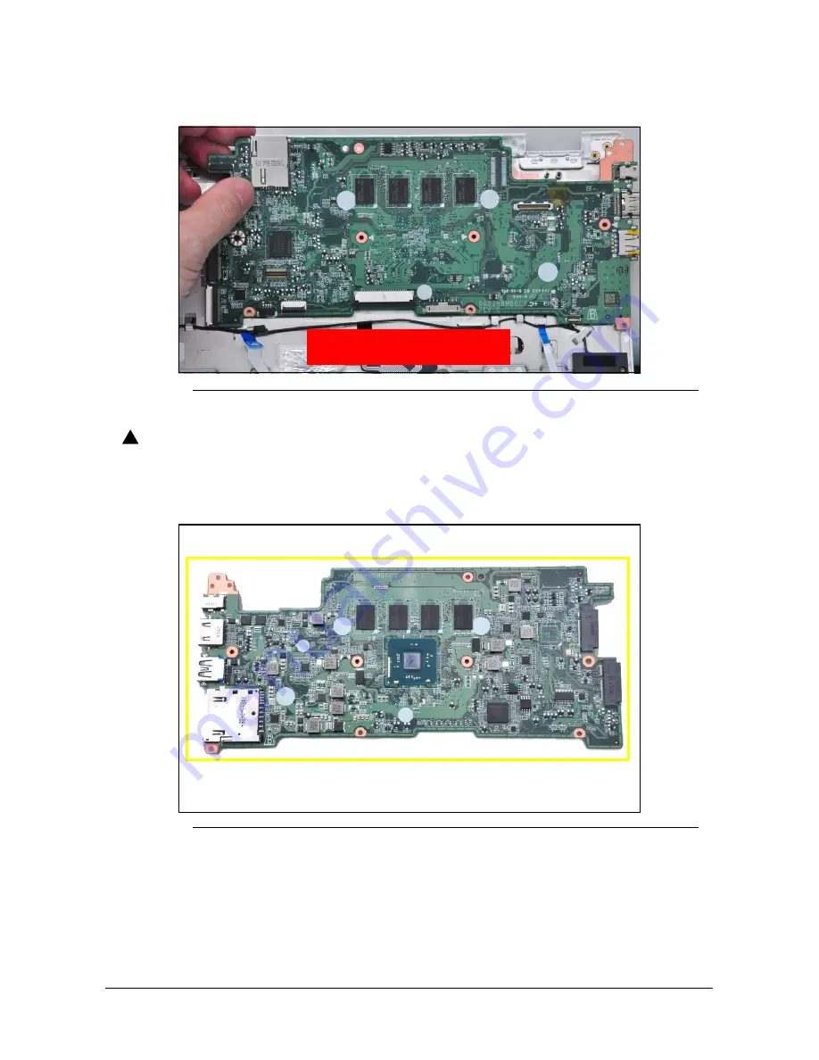
7. Remove the mainboard by gently lifting it from the top assembly (

Figure 1-22

).

Figure 1-22. Mainboard Removal

CAUTION

:

!

The touchpad FFC (Flexible Flat Cable), the LED Board FFC and the keyboard 
FPC (Flexible Printed Circuit) can be damaged if removed while the 
mainboard connectors are locked. Make sure all cables are moved away from 
the device to avoid damage during removal. 

Figure 1-23. Mainboard

IMPORTANT

:

+

Circuit boards >10 cm² have been highlighted with a yellow rectangle as 
shown in 

Figure 1-23

. Remove the circuit board and follow local 

regulations for disposal.

WEEE Annex VII Component:
Mainboard 

Summary of Contents for Chromebook C738T

Page 1: ...Acer Chromebook CB5 132T C738T LIFECYCLE EXTENSION GUIDE ...

Page 2: ...i Self Repair 1 1 Disassembly Procedures 1 2 Troubleshooting 1 25 FRU Field Replaceable Unit List 1 29 Check for updates yourself 1 33 Factory reset your Chromebook 1 34 ...

Page 3: ...TE For replacement parts always use only Acer certified components in order to safeguard quality optimum system performance stability and reliability of the product NOTE NOTE Any damage to the product that occur during self repair or which has occurred as a result of a careless or unsuccessful self repair attempt is not covered by the standard product warranty Software Recovery 0 This product has ...

Page 4: ...yourself by using a wrist grounding strap or by periodically touching an unpainted metal surface at the same time as touching a connector on the back of the computer Take off any metal objects on your arms or fingers such as bracelets rings or watches and make sure your hands are completely dry Even if your unit is unplugged there may still be some remaining electric charge If a component does not...

Page 5: ...Disassembly Procedures 1 3 WEEE Annex VII Component 0 These components are classified as requiring selective treatment I O board Battery pack WLAN module Touchpad module Mainboard LCD panel ...

Page 6: ...rocedures 1 Place the system on a stable work surface 2 Remove AC adapter A from the system and peripherals Figure 1 1 3 Remove the SD card from the SD card slot B Figure 1 1 4 Remove all cables from system Figure 1 1 AC Adapter Outlet SD Card Removal NOTE NOTE Make sure the system is completely powered off A B ...

Page 7: ...om side is up 2 Remove eleven 11 screws from the base cover Figure 1 2 Figure 1 2 Base Cover Screw Location 3 Connect the AC adapter to the system 4 Flip the system over and then open the LCD module to a 90 degree angle the system will automatically start up Figure 1 3 Figure 1 3 Battery Cut off ...

Page 8: ...C adapter immediately Figure 1 4 Figure 1 4 Battery Cut off IMPORTANT Make sure the display is dark the system is completely powered off and the AC adapter is removed from the system 6 Close the LCD module and carefully flip the system over 7 Carefully pry up the base cover starting from the right side Figure 1 5 Figure 1 5 Base Cover Removal A B C ...

Page 9: ...e mainboard connector Figure 1 6 10 Disconnect the IO board FFC B from the mainboard connector and gently peel it away from the top assembly Figure 1 6 CAUTION The IO Board FFC Flexible Flat Cable can be damaged if removed while the mainboard connector is locked Figure 1 6 Base Cover Removal 11 Remove the base cover Figure 1 7 Figure 1 7 Base Cover Removal A B ...

Page 10: ...Figure 1 8 2 Disconnect the IO Board FFC A from the IO Board connecter B and remove it 3 Remove the one 1 screw D securing the IO board in place Figure 1 8 Figure 1 8 IO Board Screw Location 4 Remove the USB board from the base cover Figure 1 9 Figure 1 9 IO Board Removal D A C B A E B WEEE Annex VII Component I O board ...

Page 11: ...Disassembly Procedures 1 9 CAUTION The IO board FFC Flexible Falt Cable can be damaged if removed while the IO board connector is locked ...

Page 12: ...ver Removal 1 Remove two 2 screws A securing the battery pack in place Figure 1 10 Figure 1 10 Battery Screw Location 2 Lift up the top edge of the battery pack to remove it from the system Figure 1 11 Figure 1 11 Battery Pack Removal A WEEE Annex VII component Battery A B ...

Page 13: ...Disassembly Procedures 1 11 IMPORTANT Follow local regulations for battery disposal ...

Page 14: ...tery Pack Removal 1 Find the WLAN module A on the top assembly Figure 1 12 Figure 1 12 Component Location 2 Disconnect WLAN antennas B connected to the WLAN card Figure 1 13 3 Remove one 1 screw C securing the WLAN module in place Figure 1 13 Figure 1 13 WLAN Pins Screw Location A C D B E F C B ...

Page 15: ...Disassembly Procedures 1 13 4 Remove the WLAN module A from the mainboard connector D Figure 1 14 Figure 1 14 WLAN Module Removal A D WEEE Annex VII Component WLAN module ...

Page 16: ...eDP cable B from the mainboard connector C Figure 1 15 3 Disconnect the G sensor control cable D from the mainboard Figure 1 15 Figure 1 15 WLAN Antenna eDP Cable Location 4 Place the system on a flat surface and open the LCD module D to a 120 degree angle as shown in Figure 1 16 5 Remove four 4 screws E securing the LCD module D in place Figure 1 16 Figure 1 16 LCD Module Screw Location A B C D D...

Page 17: ...rocedures 1 15 6 Lift the LCD module D away from the top assembly Figure 1 17 Figure 1 17 LCD Module Removal CAUTION Make sure all cables and antennas are moved away from the device to avoid damage during removal D ...

Page 18: ...o Figure 1 12 2 Disconnect the touchpad FFC A from the mainboard connector B Figure 1 18 3 Disconnect the touchpad FFC A from the touchpad connector C Figure 1 18 4 Remove the touchpad FFC A from the system Figure 1 18 5 Remove three 3 screws E securing the touchpad module in place Figure 1 18 Figure 1 18 Touchpad FFC and Screw Location A B C E ...

Page 19: ...tape F covering the touchpad module Figure 1 19 Figure 1 19 Touchpad Tape Location 7 Lift up the top edge of the touchpad module G to remove it from the top assembly Figure 1 20 Figure 1 20 Touchpad Module Removal F G WEEE Annex VII Component Touchpad module ...

Page 20: ...the speaker cable from the mainboard connector A Figure 1 21 3 Disconnect the touchpad FFC from the mainboard connector C Figure 1 21 4 Disconnect the keyboard FPC from the mainboard connector D Figure 1 21 5 Disconnect the LED Board FFC from the mainboard connector E Figure 1 21 6 Remove three 3 screws F G securing the mainboard in place Figure 1 21 Figure 1 21 Mainboard Connector Screw Location ...

Page 21: ...yboard FPC Flexible Printed Circuit can be damaged if removed while the mainboard connectors are locked Make sure all cables are moved away from the device to avoid damage during removal Figure 1 23 Mainboard IMPORTANT Circuit boards 10 cm have been highlighted with a yellow rectangle as shown in Figure 1 23 Remove the circuit board and follow local regulations for disposal WEEE Annex VII Componen...

Page 22: ...Prerequisite LCD Module Removal 1 Find the LCD panel C on the LCD cover Figure 1 24 Figure 1 24 LCD Module Component Location 2 Pry open the top edge of the LCD Assembly Figure 1 25 Figure 1 25 LCD Module Top Edge C WEEE Annex VII component LCD Panel ...

Page 23: ...ssembly Procedures 1 21 3 Pry open the left edge of the LCD Assembly Figure 1 26 Figure 1 26 LCD Module Left Edge 4 Pry open the right edge of the LCD Assembly Figure 1 27 Figure 1 27 LCD Module Right Edge ...

Page 24: ... hinge cap to remove the left hinge cap stopper B Figure 1 28 Figure 1 28 LCD Module Left Hinge Cap Stopper 6 Pull the WLAN antennas C out of the right hinge cap to remove the right hinge cap stopper D Figure 1 29 Figure 1 29 LCD Module Right Hinge Cap Stopper B A D C ...

Page 25: ...ape covering the eDP connector and disconnect the eDP cable from the LCD panel connector E Figure 1 30 8 Remove the LCD panel Figure 1 30 eDP Connector Location CAUTION Make sure the eDP and camera cable is moved away from the device to avoid damage during LCD Panel removal E ...

Page 26: ...e Speaker module LED board and Mainboard have been disassembled prior removing the top assembly NOTE NOTE The keyboard is included as part of the top assembly and can not be disassembled In the event that the keyboard can no longer be used replace the entire top assembly Figure 1 31 Top Assembly ...

Page 27: ...more help contact Google support When to recover 0 You might want to recover if You see this error message Chrome OS is missing or damaged You ve tried other troubleshooting steps and nothing has fixed your issue You ve asked the experts in our help forum for help fixing your issue and they recommend recovery What you need to get started 0 The Chromebook with the Chrome OS is missing or damaged er...

Page 28: ...d this number look at the bottom of the error message on your Chromebook screen 5 Click Continue 6 Insert your USB flash drive or SD card into the computer 7 In the dropdown menu choose the USB flash drive or SD card you inserted 8 Click Continue 9 Click Create now 10 When you see a message saying that your recovery media is ready remove the USB flash drive or SD card from the computer Step 3 Ente...

Page 29: ...n to open the popup 6 Optional If you use the extension frequently you can pin it Optional Reuse your USB flash drive or SD card After recovering your Chromebook you ll need to erase the recovery media if you want to reuse your USB flash drive or SD card to store other files To erase the recovery media 1 On your computer open Chrome 2 At the top right click Extensions 3 To launch the extension pop...

Page 30: ...at you inserted the USB drive or SD card that you used to create recovery media If you re using the correct storage device but still see this error the storage device might not be working properly 1 Erase the storage device then try recovery again 2 Try using a different USB flash drive or SD card to recover Some USB flash drives and SD cards don t work well with recovery If you re still having pr...

Page 31: ...FRU Field Replaceable Unit List 1 29 FRU Field Replaceable Unit List Please contact your local service center to find out how to obtain the part or replace your device ...

Page 32: ...ld Replaceable Unit List Exploded Diagrams 0 Figure 1 32 System Exploded Diagram Table 1 1 System Exploded Diagram No Description 1 Top Assembly with Keyboard 2 Touchpad Module 3 Mainboard 4 Battery 1 2 5 6 8 3 7 4 ...

Page 33: ...FRU Field Replaceable Unit List 1 31 5 Speaker Module 6 Base Cover 7 WLAN Module 8 IO Board Table 1 1 System Exploded Diagram No Description ...

Page 34: ...le Unit List Figure 1 33 LCD Assembly Exploded Diagram Table 1 2 LCD Assembly Exploded Diagram No Description 1 Antennas 2 eDP and Camera Cable 3 LCD Cover 4 LCD Panel 5 LCD Hinge R 6 LCD Hinge L 7 Control Cable 1 2 3 5 7 4 6 ...

Page 35: ...t the bottom right select the time 4 Select Settings 5 At the bottom of the left panel select About Chrome OS 6 Under Google Chrome OS you ll find which version of the Chrome operating system your Chromebook uses 7 Select Check for updates 8 If your Chromebook finds a software update it will start to download automatically ...

Page 36: ...our Chromebook 2 Press and hold Ctrl Alt Shift r 3 Select Restart 4 In the box that appears select Powerwash Continue 5 Follow the steps that appear and sign in with your Google Account NOTE NOTE The account you sign in with after you reset your Chromebook will be the owner account ...

Reviews: