46
Chapter 3
General Information
Before You Begin
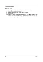
Before proceeding with the disassembly procedure, make sure that you do the following:
1.
Turn off the power to the system and all peripherals.
2.
Unplug the AC adapter and all power and signal cables from the system.
3.
Remove the battery pack.
NOTE:
There are several types of screws used to secure the product. The screws vary in length. Please refer
the picture below, group the same type of screws together during service disassembling. Please also
remember the screw location for each screw type. If you fasten the screw to the wrong location, the
screw may be too long to damage the main board.
Summary of Contents for AT3201W
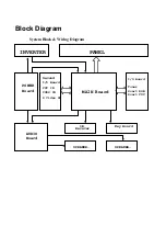
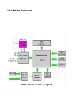
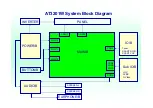
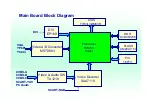
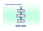
Page 4: ...LCD Main Board Block Diagram ...
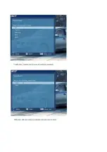
Page 8: ...OSD On Screen Display Scanning the channels First step Ask user to select the language of OSD ...
Page 9: ......
Page 10: ......
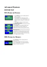
Page 11: ...Advanced Features PIP PBP POP PIP Picture in Picture PBP Picture by Picture ...
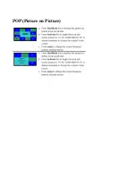
Page 12: ...POP Picture on Picture ...
Page 23: ...52 Chapter 3 ...
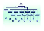
Page 24: ...AT3201W Troubleshooting Guideline ...
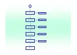
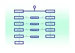
Page 32: ...3 3 Button Board I O Board Main Board END Replacement Replacement Replacement N G N G N G ...
Page 33: ...4 Main Board END Replacement N G ...
Page 34: ...5 5 IR Cable IR board Main Board END Replacement Replacement Replacement N G N G N G ...
Page 35: ...6 IO Board Main Board END Replacement Replacement N G N G ...
Page 36: ...7 7 Button Cable Button Board Main Board END Replacement Replacement Replacement N G N G N G ...
Page 37: ...8 Power Board Main Board END Replacement Replacement N G N G ...

