11
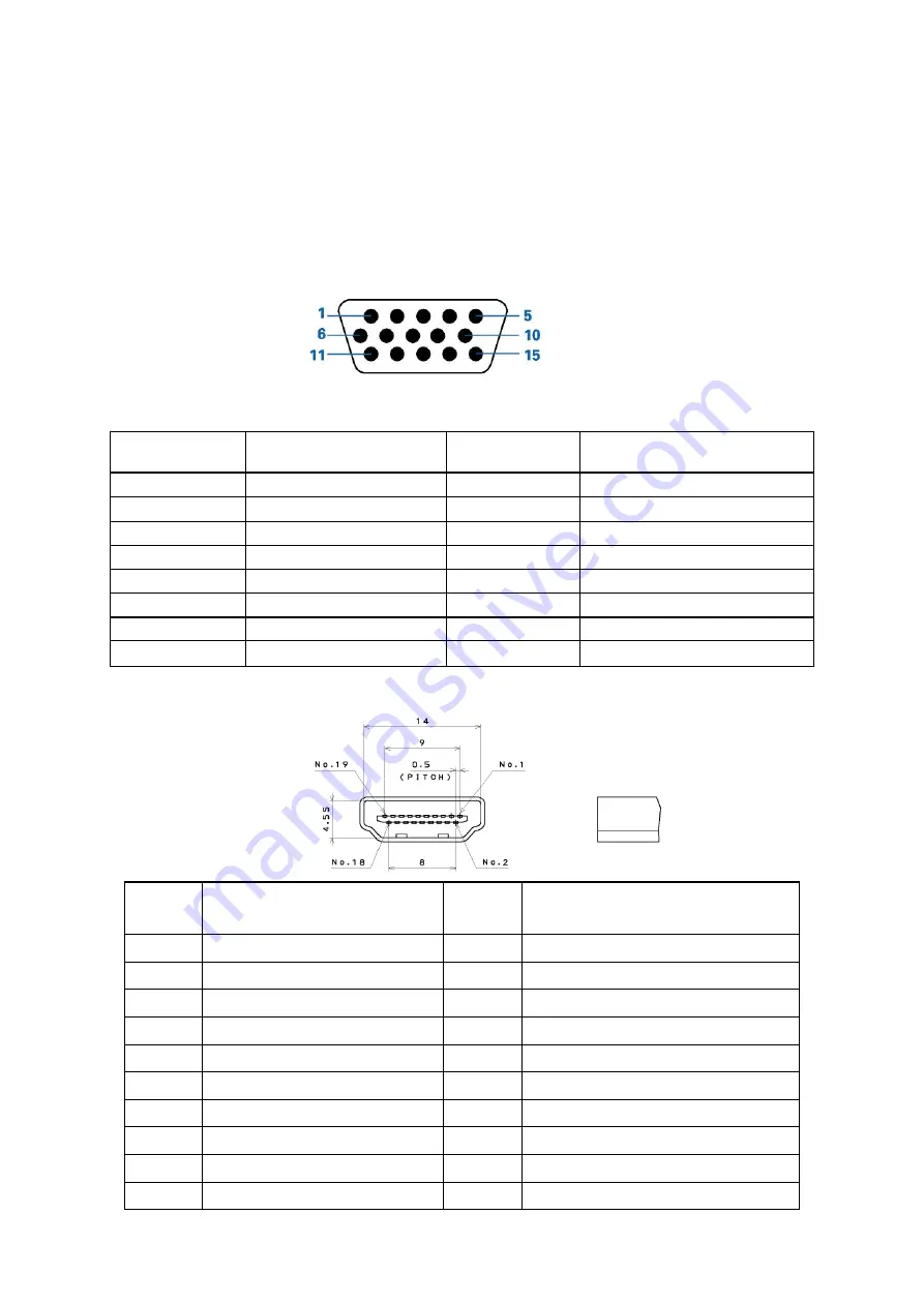
D-SUB Pin Distribution
This procedure gives you instructions for installing and using the TV display.
(1) Position the display on the desired operation and plug the power cord into a convenient AC outlet. Three-wire
power cord must be shielded and is provided as a safety precaution as it connects the chassis and cabinet to
the electrical conduct ground. If the AC outlet in your location does not have provisions for the grounded type
plug, the installer should attach the proper adapter to ensure a safe ground potential.
(2) Connect the 15-pin color display shielded signal cable to your signal system device and lock both screws on the
connector to ensure firm grounding. The connector information is as follow:
15 - Pin Color Display Signal Cable
Pin No.
Description
Pin No.
Description
1
Red
9
+5V (Supply from PC)
2 Green
10 Sync
GND
3 Blue
11 NC
4 NC
12
Bi-directional
data(SDA)
5 GND
13 H-sync
6
Red GND
14
V-sync (vclk)
7 Green
GND
15 Data
clock(SCL)
8 Blue
GND
HDMI Digital Connector Pin Assignments
Pin No.
Description
Pin No.
Description
1
TMDS Data2+
2
TMDS Data2 Shield
3
TMDS Data2-
4
TMDS Data1+
5
TMDS Data1 Shield
6
TMDS Data1-
7
TMDS Data0+
8
TMDS Data0 Shield
9
TMDS Data0-
10
TMDS Clock+
11
TMDS Clock Shield
12
TMDS Clock-
13 CEC 14
Reserved (N.C. on device)
15 SCL 16
SDA
17
DDC/CEC Ground
18
+5V Power
19
Hot Plug Detect
Summary of Contents for AT2058ML
Page 1: ...1 Acer AT2058ML AT2358ML AT2358MWL Service Guide ...
Page 7: ...7 Monitor Features General Specifications Chapter 1 ...
Page 8: ...8 ...
Page 9: ...9 AT2058ML AT2358ML AT2358MWL ...
Page 12: ...12 Factory Preset Display Modes AT2058ML AT2358ML AT2358MWL ...
Page 14: ...14 AT2358ML AT2358MWL Electrical specifications AT2058ML ...
Page 15: ...15 AT2358ML AT2358MWL ...
Page 16: ...16 Optical Specifications AT2058ML Ta 25 C VLCD 5 0V fV 60Hz fCLK 48 9MHz ...
Page 17: ...17 AT2358ML AT2358MWL Ta 25 C VLCD 5 0V fV 60Hz fCLK 119MHz ...
Page 19: ...19 Peripheral connection guide ...
Page 20: ...20 Remote Control OSD Operating instructions Using the Remote Control Chapter 3 ...
Page 21: ...21 ...
Page 22: ...22 Using the OSD Menus ...
Page 23: ...23 ...
Page 24: ...24 ...
Page 25: ...25 ...
Page 26: ...26 ...
Page 27: ...27 ...
Page 28: ...28 ...
Page 29: ...29 ...
Page 30: ...30 ...
Page 31: ...31 ...
Page 36: ...36 6 Unscrew the screws 7 Remove the speakers 8 Remove the bezel 9 Remove the main frame ...
Page 37: ...37 10 The panel ...
Page 54: ...54 PCB Layout Main Board 715G3876M0B001005K Chapter 9 ...
Page 55: ...55 ...
Page 56: ...56 ...
Page 57: ...57 Converter Board 715G4283P0G0000040 ...
Page 58: ...58 Key Board 715G4362K0A000004S LED Board 715G4396T0B000004M ...


