


6-6
FRU (Field Replaceable Unit) List
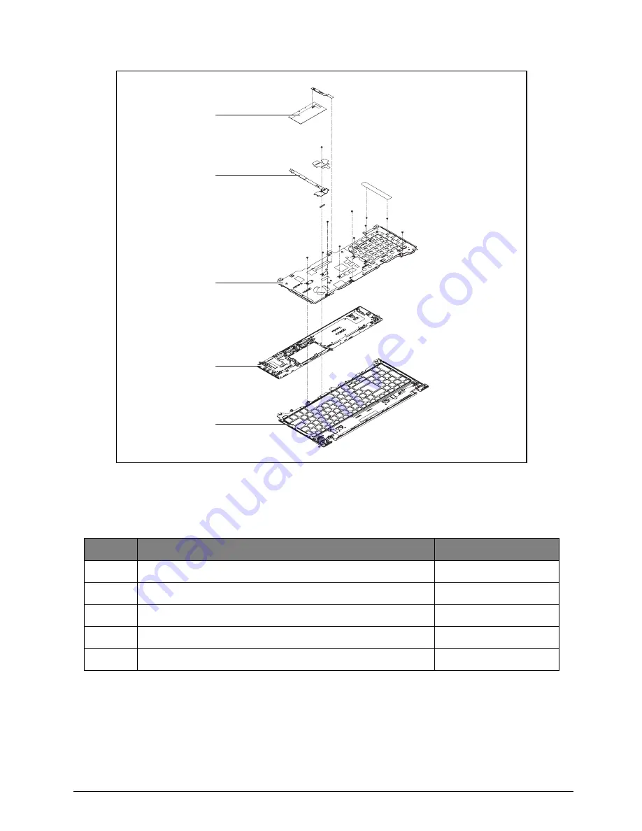
Upper Cover Assembly
Figure 6:3. Upper Cover Assembly Exploded Diagram
Table 6:3. Upper Cover Assembly Exploded Diagram
No.
Description
Acer P/N
1
TP SUPPORT RUBBER
47.M03N2.010
2
TP FFC
50.M03N2.001
3
KB SUPPORT PLATE
33.M03N2.001
4
PALMREST W/ TP
60.M04N2.001
5
UPPER CASE
60.M03N2.002
1
2
3
4
5