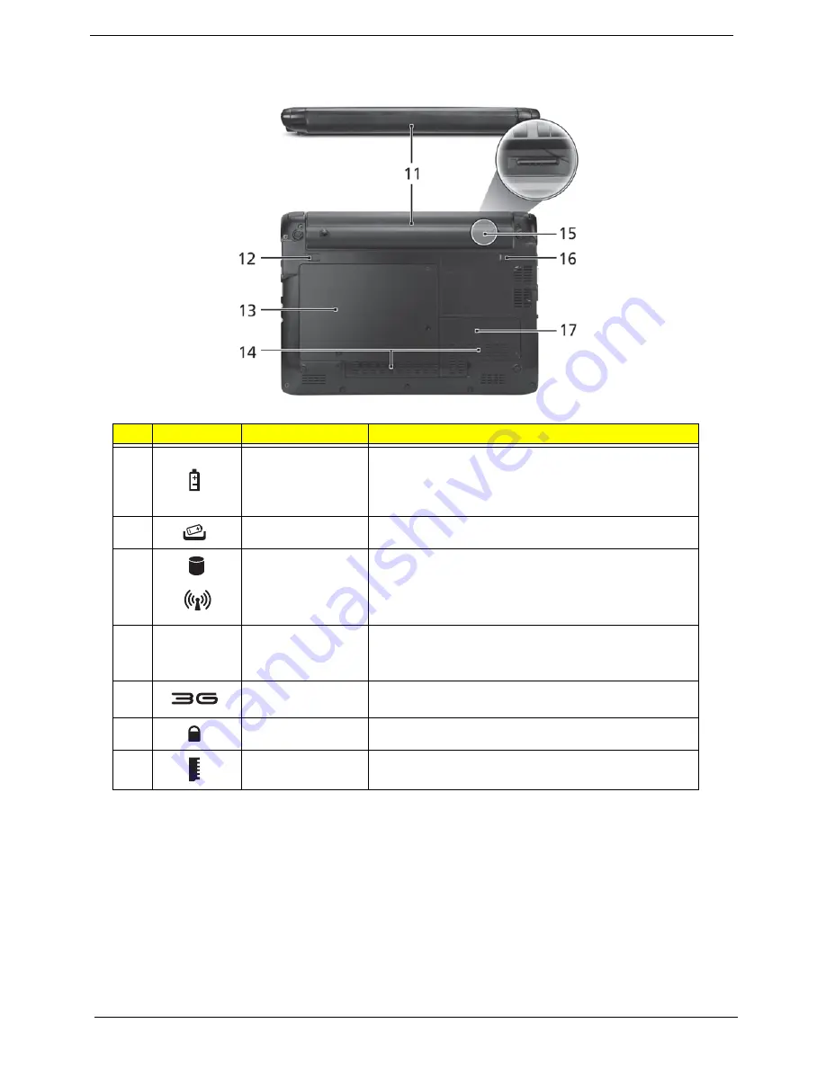
background image

8

Chapter 1

Rear and Base View

No.

Icon

Item

Description

11

Battery bay

Houses the computer's battery pack.

Note: 

The battery shown is for reference only. Your PC 

may have a different battery, depending on the model 
purchased.

12

Battery release latch Releases the battery for removal.

13

Hard disk/3G 
Wireless LAN 
communication bay

Houses the computer's hard disk/3G/ Wireless LAN 
communication (secured with screws).

14

Ventilation slots and/ 
or cooling fan

Enables the computer to stay cool, even after prolonged 
use. 

Note: 

Do not cover or obstruct the opening of the fan.

15

3G SIM card slot

Accepts a 3G SIM card for 3G connectivity (only for 
certain models).

16

Battery lock

Locks the battery in position.

17

Memory 
compartment

Houses the computer's main memory.

Summary of Contents for Aspire One AO532h

Page 1: ...NAV50 Series Service Guide PRINTED IN TAIWAN Service guide files and updates are available on the ACER CSD web for more information please refer to http csd acer com tw...

Page 2: ...II Revision History Please refer to the table below for the updates made to this service guide Date Chapter Updates...

Page 3: ...ect to the contents hereof and specifically disclaims any warranties of merchantability or fitness for any particular purpose Any Acer Incorporated software described in this manual is sold or license...

Page 4: ...bits and pieces of additional information related to the current topic WARNING Alerts you to any damage that might result from doing or not doing specific actions CAUTION Gives precautionary measures...

Page 5: ...NOT be covered in this generic service guide In such cases please contact your regional offices or the responsible personnel channel to provide you with further technical details 2 Please note WHEN OR...

Page 6: ...VI...

Page 7: ...Flash Utility 32 Remove HDD BIOS Password Utilities 33 Miscellaneous Utilities 35 Machine Disassembly and Replacement 39 Disassembly Requirements 39 Related Information 39 General Information 40 Pre d...

Page 8: ...e 89 Replacing the Mainboard 90 Replacing the I O Board 91 Replacing the Speaker Module 92 Replacing the Bluetooth Module 92 Replacing the Bridge Board 93 Replacing the LED Board 94 Replacing the Touc...

Page 9: ...Mainboard Top View 127 Mainboard Bottom View 128 Button Board 129 LED Board 130 I O Board Top View 131 I O Board Bottom View 132 Clearing Password Check and BIOS Recovery 133 Clearing Password Check...

Page 10: ...X Table of Contents...

Page 11: ...M memory interface design soDIMM slot Supports 1 GB 2 GB soDIMMs for total system memory of up to 2 GB Display and graphics 10 1 HD 1280 x 720 WXGA pixel resolution high brightness 200 nit Acer Crysta...

Page 12: ...upgradeable to 7 2 Mb s HSDPA and 5 7 Mb s HSUPA supporting receiver diversity and equalizing at 2100 MHz for 3G models LAN 10 100 Mbps Fast Ethernet Privacy control BIOS user supervisor HDD passwords...

Page 13: ...Chapter 1 3 Environment Temperature Operating 5 C to 35 C Non operating 20 C to 65 C Humidity non condensing Operating 20 to 80 Non operating 20 to 80...

Page 14: ...0 Ethernet AR8132L page 20 To I O board Card Reader ENE6252 MINI Card x1 3G PCI Express EMC1402 LCD Conn page 20 page 15 LVDS SPI INT MIC HeadPhone MIC Jack RGB page 20 USB Port X2 RJ45 SD MMC MS CONN...

Page 15: ...View No Icon Item Description 1 Acer Crystal Eye Webcam Web camera for video communication 2 Microphone Internal microphone for sound recording 3 Display screen Also called Liquid Crystal Display LCD...

Page 16: ...munication Bluetooth communication indicator Indicates the status of the Bluetooth communication 7 TouchPad Touch sensitive pointing device which functions like a computer mouse 8 Click buttons left a...

Page 17: ...move install the card Only one card can operate at any given time 6 Headphone speaker line out jack Connects to line out audio devices e g speakers headphones 7 Microphone in jack Accepts input from e...

Page 18: ...oval 13 Hard disk 3G Wireless LAN communication bay Houses the computer s hard disk 3G Wireless LAN communication secured with screws 14 Ventilation slots and or cooling fan Enables the computer to st...

Page 19: ...Function Description Power indicator Indicates the computer s power status Battery indicator Indicates the computer s battery status HDD indicator Indicates when the hard disk drive is active Num Lock...

Page 20: ...Pad keep it and your fingers dry and clean The TouchPad is sensitive to finger movement hence the lighter the touch the better the response Tapping too hard will not increase the TouchPad s responsive...

Page 21: ...uppercase Num Lock Fn F11 When Num Lock is on the embedded keypad is in numeric mode The keys function as a calculator complete with the arithmetic operators and Use this mode when you need to do a lo...

Page 22: ...connected to a network domain M Minimizes all windows R Open the Run dialog box U Open Ease of Access Center BREAK Display the System Properties dialog box SHIFT M Restore minimized windows to the de...

Page 23: ...F3 Acer ePower Management Launches Acer ePower Management in Acer Empowering Technology Fn F4 Sleep Puts the computer in Sleep mode Fn F5 Display toggle Switches display output between the display scr...

Page 24: ...Hold Alt Gr and then press the 5 key at the upper center of the keyboard NOTE Some fonts and software do not support the Euro symbol See www microsoft com typography faq faq12 htm for more information...

Page 25: ...pset ICH7M Intel 82801GBM On die 512 kB 8 way L2 cache Chipset Tiger Point Chipset NM10 ENE KB926 for Keyboard Controller Battery management Unit and RTC Realtek ALC272X GR for High Definition Audio C...

Page 26: ...160 250GB and above 5400 rpm SATA connector BTO Item Specification Vendor Model Name Seagate ST9160310AS Seagate ST9250827AS Seagate ST9250315AS HGST L9A300 HTS543225 HTS543216 WD WD2500BEVT WD1600BEV...

Page 27: ...endor InsydeH20 BIOS Version V0 12_Mac BIOS ROM type Flash BIOS ROM size 1 MB Features Support ISIPP Support Acer UI Support multi boot Suspend to RAM S3 Disk S4 Various hot keys for system control Su...

Page 28: ...ll ADCs support independent 44 1k 48k 96k 192kHz sample rate Two independent SPDIF outputs support 16 20 24 bit format and 44 1k 48k 88 2k 96k 192kHz rate Supports line level mono output Supports anal...

Page 29: ...iteon Camera Lily Type 0 3M LDV Item Specification Features 3G card in mini PCI card size Control by USB interface User accessible SIM card by battery remove Antenna Has to be placed on the sides of L...

Page 30: ...20 Chapter 1...

Page 31: ...boot device without entering BIOS SETUP Utility Navigating the BIOS Utility There are six menu options Information Main Advanced Security Power Boot and Exit Follow these instructions To choose a men...

Page 32: ...the system Manufacturer Name This field displays the manufacturer of this system UUID Universally Unique Identifier UUID is an identifier standard used in software construction standardized by the Ope...

Page 33: ...LAN remote server Option Enabled or Disabled F12 Boot Menu Enables disables Boot Menu during POST Option Enabled or Disabled D2D Recovery Enables disables D2D Recovery function The function allows th...

Page 34: ...d Press Enter to set the user password When user password is set this password protects the BIOS Setup Utility from unauthorized access The user can enter Setup menu only and does not have right to ch...

Page 35: ...er to Set 4 If desired you can opt to enable the Password on boot parameter 5 When you are done press F10 to save the changes and exit the BIOS Setup Utility Removing a Password Follow these steps 1 U...

Page 36: ...When you are done press F10 to save the changes and exit the BIOS Setup Utility If the verification is OK the screen will display as following The password setting is complete after the user presses E...

Page 37: ...press F5 to move it down the list or F6 to move it up the list Press Esc to escape the menu F1 ESC Help Exit Select Item Select Menu Change Values Select SubMenu Enter F9 F10 Setup Default Save and E...

Page 38: ...es for all SETUP item Discard Changes Load previous values from CMOS for all SETUP items Save Changes Save Setup Data to CMOS Item Specific Help Exit System Setup and save your changes to CMOS F1 ESC...

Page 39: ...e before you use the Flash utility NOTE Do not install memory related drivers XMS EMS DPMI when you use the Flash utility NOTE Please use the AC adaptor power supply when you run the Flash utility If...

Page 40: ...ge Please do not remove AC Power Source displays Item Specific Help Use or to select a device then press F5 to move it down the list or F6 to move it up the list Press Esc to escape the menu F1 ESC He...

Page 41: ...Chapter 2 31 NOTE If the AC power is not connected the following message displays Plug in the AC power to continue 5 Flash is complete when the message Flash programming complete displays...

Page 42: ...m the following steps to use the WinFlash Utility 1 Double click the WinFlash executable 2 Click OK to begin the update A progress screen displays 3 When the process is complete close all programs and...

Page 43: ...error is displayed select the Enter Unlock Password option on the screen 2 An Encode key is generated for unlocking utilities Note down this key 3 Execute the UnlockHD EXE file to create the unlock co...

Page 44: ...rument to short the U72 jumper as shown below Cleaning BIOS Passwords To clean the User or Supervisor passwords perform the following steps 1 From a DOS prompt execute clnpwd exe 2 Press 1 or 2 to cle...

Page 45: ...to be used in the DMI pool for hardware management When the BIOS displays Verifying DMI pool data it is checking the table correlates with the hardware before sending to the operating system Windows...

Page 46: ...PROM Input dmitools wp Acer Example 3 Write Serial Number to EEPROM Input dmitools ws 01234567890123456789 Example 4 Write UUID to EEPROM Create UUID from Intel WFM20 pdf Input dmitools wu Example 5 W...

Page 47: ...Chapter 2 37 3 Execute MAC BAT to write MAC information to eeprom...

Page 48: ...38 Chapter 2...

Page 49: ...wdriver Plastic tweezers NOTE The screws for the different components vary in size During the disassembly process group the screws with the corresponding components to avoid mismatch when putting back...

Page 50: ...o the following sections External components disassembly Main unit disassembly LCD module disassembly The flowcharts provided in the succeeding disassembly sections illustrate the entire disassembly s...

Page 51: ...st Step Screw Quantity Part No HDD Door M2 4 3 86 SAS02 002 HDD Carrier M3 3 4 86 SAS02 006 WLAN Module M2 3 1 86 SAS02 001 DIMM Door M2 6 1 86 SAS02 004 Back Cover M2 3 2 86 SAS02 001 M2 4 5 86 SAS02...

Page 52: ...Battery Pack 1 Turn the computer over 2 Slide the battery lock unlock latch to the unlock position 3 Slide and hold the battery release latch to the release position 1 then slide out the battery pack...

Page 53: ...Chapter 3 43 Removing the HDD Module 1 Remove the three 3 screws from the HDD Cover 2 Lift the HDD cover up to remove Step Size Quantity Screw Type HDD Cover M2 4 3...

Page 54: ...Lift the hard disk drive module out of the bay NOTE To prevent damage to the device avoid pressing down on it or placing heavy objects on top of it 5 Remove the four 4 screws two each side securing t...

Page 55: ...Chapter 3 45 Removing the DIMM Module 1 Remove one 1 screw from the DIMM door 2 Insert a plastic tool to lift the corner of the DIMM cover 3 Lift the DIMM cover clear of the device...

Page 56: ...46 Chapter 3 4 Push out the release latches on both sides of the DIMM socket to release the DIMM module 5 Remove the DIMM module...

Page 57: ...WLAN Module 1 See Removing the HDD Module on page 43 2 Disconnect the Antenna cables from the WLAN Module 3 Move the antenna away and remove the one 1 screw from the WLAN Module Step Size Quantity Scr...

Page 58: ...48 Chapter 3 4 Pull the WLAN Module from the slot NOTE When reattaching the antennas ensure the cables are tucked into the chassis to prevent damage...

Page 59: ...on page 43 2 See Removing the DIMM Module on page 45 3 See Removing the WLAN Module on page 47 4 Remove eleven 11 screws from the Back Cover Step Size Quantity Screw Type Back Cover Green Callout M2...

Page 60: ...represent the final product color or configuration Main Unit Disassembly Flowchart Screw List Step Screw Quantity Part No Upper Cover M2 6 7 86 SAS02 004 LED Board M2 3 1 86 SAS02 001 Bridge Board M2...

Page 61: ...Chapter 3 51 I O Board M2 3 1 86 SAS02 001 Mainboard M2 3 1 86 SAS02 001 Thermal Module M2 4 3 86 SAS02 002 Step Screw Quantity Part No...

Page 62: ...nd open the lid to the full extent 3 Unlock the center securing latch by pressing down with a plastic tool IMPORTANT The use of metal tools may damage the outer casing Use only plastic tools 4 Grasp t...

Page 63: ...Chapter 3 53 6 Disconnect the FFC and lift the Keyboard clear of the device...

Page 64: ...See Removing the Keyboard on page 52 2 Disconnect the following cables from the Mainboard Release the locking latch on A as shown Disconnect A from the Mainboard Release the locking latch on B as sho...

Page 65: ...r Remove the seven 7 securing screws 4 Slide a plastic tool between the Upper and Lower Covers to unlock the guide hooks underneath 5 Grasp the right side of the upper cover and pry apart Step Size Qu...

Page 66: ...56 Chapter 3 6 Lift the left side of the Upper Cover away from the Lower Cover 7 Lift the Upper Cover clear of the device...

Page 67: ...e Removing the Upper Cover on page 54 2 Remove two 2 screws from the Touchpad board 3 Unlock the Touchpad cable connector and disconnect the cable 4 Lift the Touchpad Board clear of the device Step Si...

Page 68: ...Chapter 3 Removing the LED Board 1 See Removing the Upper Cover on page 54 2 Remove one 1 screw from the LED Board 3 Lift the LED Board clear of the device Step Size Quantity Screw Type LED Board M2 3...

Page 69: ...e Removing the Upper Cover on page 54 2 Remove two 2 screws from the Bridge Board 3 Disconnect the Bridge Board from the connectors underneath by carefully lifting the board clear of the device Step S...

Page 70: ...hapter 3 Removing the Bluetooth Module 1 See Removing the Upper Cover on page 54 2 Disconnect the Bluetooth to Mainboard cable 3 Lift the Bluetooth Module left side first to remove it from the Upper C...

Page 71: ...oving the Speaker Module 1 See Removing the Upper Cover on page 54 2 Remove the four 4 securing screws two for each Speaker 3 Disconnect the Speaker cable as shown Step Size Quantity Screw Type Speake...

Page 72: ...62 Chapter 3 4 Lift out the left speaker while removing the Speaker cable from the cable channel Ensure that the cable is free from all cable clips 5 Lift the Speaker Module clear of the Lower Cover...

Page 73: ...Chapter 3 63 Removing the I O Board 1 See Removing the Upper Cover on page 54 2 Remove one 1 screw from the I O Board 3 Disconnect the I O Board cable Step Size Quantity Screw Type I O Board M2 3 1...

Page 74: ...64 Chapter 3 4 Remove the I O Board by angling the board upwards and pulling it out of the connector bracket as shown...

Page 75: ...65 Removing the Mainboard 1 See Removing the Speaker Module on page 61 2 Remove the LVDS adhesive tape 3 Disconnect the LVDS cable and remove the cable from the cable channel 4 Disconnect the AC cable...

Page 76: ...securing the Mainboard to the Lower Cover 6 Lift the Mainboard from the side opposite the connector bracket then remove it from the Lower Cover 7 Remove the DC in port from the Lower Cover Step Size...

Page 77: ...g the Thermal Module 1 See Removing the Mainboard on page 65 2 Disconnect the Fan cable from the Mainboard 3 Remove the three 3 securing screws from the Thermal Module Step Size Quantity Screw Type Th...

Page 78: ...68 Chapter 3 4 Lift the Thermal Module clear of the Mainboard...

Page 79: ...hannels and clips are used and that the cables are replaced in the same position 1 See Removing the Mainboard on page 65 2 Turn the device over and pull the white antenna cable out of the cable channe...

Page 80: ...ack antenna cable through the Lower Cover and release it from the cable channel as shown 5 Remove two 2 screws from the LCD Assembly 6 Lift the LCD Assembly clear of the device Step Size Quantity Scre...

Page 81: ...lor or configuration The following procedure outlines the steps to disassemble the LCD Module on models with 3G functionality Models that do not support 3G do not require the removal of the yellow and...

Page 82: ...aps and two 2 screws from the LCD Bezel 3 Carefully pry the LCD Bezel from the LCD Assembly using both hands If necessary use a plastic pry to release the corners of the bezel When all the guide hooks...

Page 83: ...ng the LCD Bezel on page 72 CAUTION Do not use excessive force when handling the Web Camera Board 2 Disconnect the cable from the Web Camera Board as shown 3 Detach the Web Camera Board while being ca...

Page 84: ...Camera Board on page 73 2 Remove the four 4 securing screws from the LCD Panel 3 Remove the LVDS foil tab and pull the LVDS cable away from the channel as shown 4 Lift the LCD Panel clear of the LCD...

Page 85: ...move the foil tabs from the Microphone set while lifting the cable away from the cable channel 3 Continue removing the foil tabs and pulling the cable away The cable channel is highlighted between the...

Page 86: ...tennas 1 See Removing the LCD Panel on page 74 2 Peel back the foil tabs on the black antenna cable 3 Pull the cable away from the cable channel which is highlighted between the green lines 4 Pry the...

Page 87: ...Chapter 3 77 5 Peel back the foil tabs on the white antenna cable 6 Pull the cable away from the cable channel which is highlighted between the green lines 7 Pry the antenna pad clear of the bracket...

Page 88: ...ng the Microphone Set on page 75 2 Turn the LCD Panel over and peel away the LVDS cable 3 Detach the clear connector tape and disconnect the LVDS cable 4 Remove four 4 screws that secure the LCD Panel...

Page 89: ...Chapter 3 79 5 Remove two 2 brackets from the LCD Panel...

Page 90: ...odule Reassembly Procedure Replacing the LCD Brackets 1 Replace two 2 brackets to the LCD Panel 2 Secure the LCD Panel using four 4 screws 3 Connect the LVDS cable to the LCD Panel and reattach the cl...

Page 91: ...ith the camera module If the cable is misaligned the camera module may shift causing the camera to sit in the wrong location 4 Lay the cable across the LCD Panel in the area indicated between the gree...

Page 92: ...e along the cable channel which is highlighted between the green lines 3 Adhere the foil tabs to the white antenna cable 4 Place the antenna pad in the bracket 5 Run the cable along the cable channel...

Page 93: ...Replace the Microphone set and fold over the foil tab 2 Run the cable along the cable channel while adhereing the foil tabs The cable channel is highlighted between the green lines 3 Secure the last f...

Page 94: ...84 Chapter 3 Replacing the LCD Panel 1 Place the LCD Panel in the LCD Bracket 2 Secure the LCD Assembly using four 4 screws 3 Run the LVDS cable in the cable channel while replacing the foil tabs...

Page 95: ...ing the Camera Board CAUTION Do not handle the Web Camera Board with excessive force 1 Attach the Web Camera Board to the inside of the bracket Press down to secure the board in place 2 Connect the Ca...

Page 96: ...hapter 3 Replacing the LCD Bezel 1 Place the LCD Bezel on the LCD Assembly Press down on all sides to make sure the bezel is fitted securely 2 Secure the LCD Bezel using two 2 screws and two 2 screw c...

Page 97: ...eassembly Procedure Replacing the LCD Module 1 Place the LCD Module on the Lower Cover 2 Secure the LCD Module using two 2 screws 3 Run the black antenna cable through the cable channel and pull it th...

Page 98: ...nna cable through the cable channel and pull it through the casing as shown 5 Turn the device over and continue running the white antenna cable through the cable channel Make sure the cable is secured...

Page 99: ...e in place before replacing the Thermal Module The following thermal pads are approved for use Eapus XR PE 1 Align the screw holes on the Thermal Module and Mainboard and replace the module 2 Secure t...

Page 100: ...the Lower Cover 2 Replace the Mainboard by lining up the connector bracket before replacing completely 3 Secure the Mainboard using one 1 screw 4 Connect the AC cable 5 Run the LVDS cable along the ca...

Page 101: ...Replacing the I O Board 7 Replace the LVDS adhesive tape 1 Replace the I O Board by lining up the board with the connector bracket as shown 2 Connect the I O cable 3 Secure the I O Board by replacing...

Page 102: ...Replacing the Bluetooth Module 1 Secure the Speaker Module by replacing four 4 screws 2 Connect the Speaker cable as shown 1 Attach the Bluetooth Board to the casing Press down to secure it in place 2...

Page 103: ...connectors located on the underside of the Bridge Board Reconnect the Bridge Board by lining the board up with the connectors as shown NOTE Press down firmly to ensure the two connectors are properly...

Page 104: ...the LED Board Replacing the Touchpad Board 1 Place the Touchpad Board in the device while pressing down on the FFC to adhere it to the Upper Cover 1 Place the LED Board in the device 2 Secure the LED...

Page 105: ...Chapter 3 95 2 Secure the Touchpad Board using two 2 screws 3 Connect the Touchpad cable and lock the connector...

Page 106: ...96 Chapter 3 Replacing the Upper Cover 1 Place the Upper Cover on the Lower Cover Press down firmly to ensure that the covers are locked together 2 Secure the Upper Cover using seven 7 screws...

Page 107: ...Chapter 3 97 3 Reconnect the following cables to the Mainboard Connect A to the Mainboard Secure the locking latch on A as shown Connect B to the Mainboard Secure the locking latch on B as shown B A...

Page 108: ...Keyboard FPC in to the Mainboard connector 2 Close the FPC locking latch as shown 3 Turn the Keyboard over and slide it in the direction of the arrow Press down around the edges of the Keyboard to en...

Page 109: ...Replacing the DIMM Module 1 Replace the WLAN card 2 Secure the WLAN module using one 1 screw 3 Connect two 2 antenna cables to the WLAN module 1 Line the DIMMcard up with the slot 2 Push the DIMM car...

Page 110: ...3 3 Replace the DIMM cover by first lining up the guide hooks on the top edge 4 Press down on the cover to lock all guide hooks The cover should be flush with the device 5 Secure the DIMM cover using...

Page 111: ...ure the Carrier to the HDD by replacing the four 4 screws 2 Insert the HDD Module into the Lower Cover as shown 3 Slide the HDD Module in the direction of the arrow to connect the interface 4 Replace...

Page 112: ...3 Replacing the Battery Pack 1 Slide and hold the battery release latch to the release position 1 then insert the battery pack in to the main unit 2 2 Slide the battery lock unlock latch to the lock p...

Page 113: ...able with the verified symptom to determine which page to go to 4 If the Issue is still not resolved see Online Support Information on page 213 Symptoms Verified Go To Power On Issue Page 104 No Displ...

Page 114: ...let 2 Remove any extension cables between the computer and the outlet 3 Remove any surge protectors between the computer and the electrical outlet Plug the computer directly into a known good electric...

Page 115: ...tton for 10 seconds Reconnect the power and reboot the computer 4 Connect an external monitor to the computer and switch between the internal display and the external display is by pressing Fn F5 on t...

Page 116: ...e Resolution slider to the desired resolution e Click Apply and check the display Readjust if necessary 6 Roll back the video driver to the previous version if updated 7 Remove and reinstall the video...

Page 117: ...efective FRUs Built In Keyboard Failure If the built in Keyboard fails perform the following actions one at a time to correct the problem Do not replace non defective FRUs Start CheckLCD module Swap L...

Page 118: ...esn t work perform the following actions one at a time to correct the problem Do not replace non defective FRUs Start CheckM B T P FFC Re assemble the T P FFC to M B OK NG Check Logic Upper OK Swap Re...

Page 119: ...iver to the previous version if updated recently 4 Remove and reinstall the audio driver 5 Ensure that all volume controls are set mid range a Click the volume icon on the taskbar and drag the slider...

Page 120: ...e system and file settings from a known good date using System Restore If the issue is not fixed repeat the preceding steps and select an earlier time and date 10 Reinstall the Operating System 11 If...

Page 121: ...t Show Disabled Devices clear by default 3 The microphone appears on the Recording tab 4 Right click on the microphone and select Enable 5 Select the microphone then click Properties Select the Levels...

Page 122: ...o locate and resolve issues with the computer i When complete click Finish If an issue is discovered follow the onscreen information to resolve the problem 4 Run the Windows Memory Diagnostic Tool For...

Page 123: ...f the rightside USB port fails perform the following actions one at a time to correct the problem Do not replace non defective FRUs Start CheckIO B to M B CONN Re assemble the IO B CONN to M B OK NG C...

Page 124: ...test fails perform the following actions one at a time to correct the problem Do not replace non defective FRUs Start CheckWL antennato WLcard Re assemble the antenna to WLcard OK NG Check antenna OK...

Page 125: ...ils perform the following actions one at a time to correct the problem Do not replace non defective FRUs Start Check3G antennato 3G card Re assemble the antenna to 3G card OK NG Check antenna OK Swap...

Page 126: ...he switches fail perform the following actions one at a time to correct the problem Do not replace non defective FRUs Start CheckIO B to M B FFC Re assemble the IO B FFC to M B OK NG CheckIO B and FFC...

Page 127: ...problem Do not replace non defective FRUs Power Button Failure If the Power Button fails perform the following actions one at a time to correct the problem Do not replace non defective FRUs START Fan...

Page 128: ...e is not fixed repeat the preceding steps and select an earlier time and date 9 Run the Event Viewer to check the events log for errors For more information see Windows Help and Support 10 Roll back t...

Page 129: ...er a short circuit is suspected or whether the system is inoperative Follow these procedures to isolate the failing FRU do not isolate non defective FRU NOTE Verify that all attached devices are suppo...

Page 130: ...Discharge If any problems such as incorrect CMOS settings the CMOS data can be cleared by short circuiting the CMOS jumpers Remove the Back Cover and use a metal conductivity tool to short circuit th...

Page 131: ...common CAS latency between the DIMMS and the MCH 0x09 Determine the memory frequency and CAS latency to program 0x10 Determine the smallest common TRAS for all DIMMs 0x11 Determine the smallest commo...

Page 132: ...re ECC init 0x28 Report status code of every memory range 0x50 Get the root bridge handle 0x51 Notify pci bus driver starts to program the resource 0x58 Reset the host controller 0x5A IdeBus begin ini...

Page 133: ...0xAA PEI_PLATFORM_STAGE2 0xAC PEI_SB_SMBUS_ARP_DISABLED 0x0F PEI_HOST_TO_SYSTEM 0x40 PEI_MEMORY_INIT 0x41 PEI_S3_RESUME 0xAD PEI_CLOCK_GEN 0xAB PEI_OP_PRESENCE 0xAE PEI_FIND_FV 0x16 PEI_H2O_DEBUG_IO 0...

Page 134: ..._BUS 0xE9 ISA_SERIAL 0xED BUS_PCI_UNDI 0xEC PCI_BUS 0xF6 BOOT_PRIORITY 0xF7 FVB_SERVICE 0xF8 ACPI_PLATFORM 0xFB PCI_HOT_PLUG 0xFC DXE_PLATFORM 0xFD PLATFORM_IDE 0x97 SMBIOS 0x98 MEMORY_SUB_CLASS 0x99...

Page 135: ...NCH 0x9E HII_DATABASE 0x9F OEM_SETUP_BROWSER 0x8C OEM_BADGING_SUPPORT 0xF9 SETUP_MOUSE 0x72 MONITOR_KEY 0xBD PLATFORM_BDS 0x8D RESERVED 0x8E RESERVED 0x8F RESERVED 0xA0 DXE_H2O_DEBUG_IO 0xB3 DXE_TPM_T...

Page 136: ...CCESS 0xDE SMM_CONTROL 0xCC SMM_BASE 0xD2 SMM_RUNTIME 0xDF SB_SMM_DISPATCH 0xD0 SMM_THUNK 0xCA SMM_ACPI_SW_CHILD 0xFE SMM_PLATFORM 0xD8 SMM_GMCH_MBI 0x90 SMM_FW_BLOCK_SERVICE 0x91 SMM_VARIABLE 0x92 SM...

Page 137: ...m Description SW1 NAV50 Power Button LED1 NAV50 Power LED PJP1 AC IN Jack JP3 SIM Connector JLVDS1 LCD Connector JP18 LED B Connector JP23 NAV60 Power B Connector JKB1 Internal Keyboard Connector JP11...

Page 138: ...ter 5 Mainboard Bottom View Item Description PJP2 Battery Connector JCRT1 CRT Connector JUSB1 USB Connector JUSTB2 USB Connector JHDD1 HDD Connector JDIM1 WWAN Connector JP12 FAN Connector JDIM1 RAM C...

Page 139: ...Chapter 5 129 Button Board Item Description SW1 T P Left Button SW2 T P Right Button...

Page 140: ...130 Chapter 5 LED Board Item Description LED1 Power Suspend LED LED2 Battery LED LED3 Media LED LED4 Num LED LED5 Cap LED LED6 WWAN WLAN LED LED7 BT LED...

Page 141: ...Chapter 5 131 I O Board Top View Item Description JP21 Function B Connector JP4 Internal MIC JP20 Speaker CONN JREAD1 Card Reader Socket JP2 Bridge B Connector...

Page 142: ...132 Chapter 5 I O Board Bottom View Item Description JRJ45 RJ45 Connector JUSB1 USB Connector JMIC1 MIC In Jack JHP1 Head Phone Jack JMINI1 WLAN Connector...

Page 143: ...he password check users need to short the HW Gap to clear the password by the following steps Power Off the system and remove HDD AC and Battery from the machine Open the back cover of the machine and...

Page 144: ...isis Diskette should be prepared ready in hand The Crisis Diskette could be made by executing the Crisis Disk program in another system with Windows XP OS Follow the steps below 1 Plug in the USB disk...

Page 145: ...ons a part number change is made it will not be noted on the printed Service Guide For ACER AUTHORIZED SERVICE PROVIDERS your Acer office may have a DIFFERENT part number code from those given in the...

Page 146: ...Description Part Number 1 LCD Assembly 6M SAL02 001 2 Upper Cover 60 SAL02 001 3 Bridge Board 55 SAS02 002 4 Mainboard MB SAL02 001 5 Speaker Module 23 SAT02 001 6 DC in Port 50 SAS02 002 7 Lower Cov...

Page 147: ...Chapter 6 137 Rear Assembly Item Description Part Number 1 HDD Door 42 SAL02 001 2 DIMM Door 42 SAL02 002 3 Lower Cover 60 SAM02 001 1 2 3...

Page 148: ...138 Chapter 6 Upper Cover Assembly Item Description Part Number 1 TouchPad Board 2 LED Board 55 SAS02 004 3 Upper Cover 60 SAL02 001 1 2 3...

Page 149: ...EM770W LC 21300 008 3G UNDP 1 LC 21300 005 ERICSSON F3307 850MHZ LC 21300 038 FOXCONN BROADCOM BCM970010 MEDIA PROCESSOR MINI CARD LINK W H 264 VC1 MPEG2 LA 20500 003 FOXCONN QUARTICS QV1721 MEDIA CO...

Page 150: ...CASE ASSY FOR W O 3G BLACK 60 SAL02 003 LOWER CASE ASSY FOR W 3G WHITE 60 SAT02 001 LOWER CASE ASSY FOR W O 3G WHITE 60 SAS02 005 HDD DOOR BLACK 42 SAL02 001 HDD DOOR WHITE 42 SAS02 001 RAM DOOR BLACK...

Page 151: ...ortuguese Texture KB I100A 017 Keyboard ACER NT0T JV01_PT Internal 10 Standard 85KS Black Spanish Texture KB I100A 020 Keyboard ACER NT0T JV01_PT Internal 10 Standard 85KS Black US w Canadian French T...

Page 152: ...NT0T White JV01_PT Internal 10 Standard 85KS White Hungarian Texture KB I100A 040 Keyboard ACER NT0T White JV01_PT Internal 10 Standard 85KS White Norwegian Texture KB I100A 045 Keyboard ACER NT0T Whi...

Page 153: ...10 1 WSVGA Glare W ANTENNA CCD PINK 6M SAS02 004 ASSY LED MODULE 10 1 WXGA Glare W ANTENNA CCD PINK 6M SAS02 006 ASSY LED MODULE 10 1 WSVGA None Glare W ANTENNA CCD 3G BLUE 6M SAM02 001 ASSY LED MODU...

Page 154: ...TEL LF N450 NM10 NON 3G MB SAL02 001 MAINBOARD AO532H INTEL LF N450 NM10 3G MB SAM02 001 HEATSINK THERMAL MODULE 60 SAS02 009 SPEAKER MIC SET FOR W 3G 23 SAT02 001 MIC SET FOR W O 3G 23 SAS02 001 SPEA...

Page 155: ...SCREW SCREW 2D 3L K 4 5D ZK NL 86 SAS02 001 SCREW 2 0D 4 0L K 3 6D ZK NL CR3 86 SAS02 002 SCREW 2D 4 0L K 4 0D NI NL 0 3T 86 SAS02 003 SCREW 2D 6L K 4 6D ZK NL CR3 86 SAS02 004 SCREW 2 0D 6 0L K 4 3D...

Page 156: ...34 AO532h 2Db SNW7ST32EMSTME6 MC UMACbk 1 1G 160 3L2 2 5R CBSD_bg_0 3D_GEb_ES61 ATMN450B EMEA Middle East LU SAL0D 068 AO532h 2Db SNW7ST32EMSTME2 MC UMACbk 1 1G 250 3L2 2 5R CBSD_bg_0 3D_GEb_AR11 ATMN...

Page 157: ...1 MC UMACbk 1 1G 160 3L2 2 5R CBSD_bg_0 3D_GEb_TR31 ATMN450B EMEA Algeria LU SAL0D 074 AO532h 2Db SNW7ST32EMSTDZ1 MC UMACbk 1 1G 250 3L2 2 5R CBSD_bg_0 3D_GEb_ES81 ATMN450B EMEA Middle East LU SAL0D 0...

Page 158: ...5R CBSD_bg_0 3D_GEb_PT11 ATMN450B EMEA Germany LU SAL0D 141 AO532h 2Db SNW7ST32STDE1 MC UMACbk 1 1G 250 BT 6L2 2 5R CBSD_bg_0 3D_GEb_DE13 ATMN450B EMEA Holland LU SAL0D 140 AO532h 2Db SNW7ST32STNL1 M...

Page 159: ...1G 250 3L2 2 5R CBSD_bg_0 3D_GEb_PT11 ATMN450B EMEA Luxembourg LU SAL0D 099 AO532h 2Db SNW7ST32STLU3 MC UMACbk 1 1G 250 3L2 2 5R CBSD_bg_0 3D_GEb_IT41 ATMN450B EMEA Germany LU SAL0D 098 AO532h 2Db SN...

Page 160: ...SD_bg_0 3D_GEb_EN12 ATMN450B EMEA Greece LU SAL0B 099 AO532h 2Bb AOXPHSTGR1 MC UMACbk 1 1G 160 6L2 2 5R CBSD_bg_0 3D_GEb_EL32 ATMN450B EMEA Middle East LU SAL0B 098 AO532h 2Bb EM AOXPHSTME9 MC UMACbk...

Page 161: ...D_GEb_RU24 ATMN450B EMEA South Africa LU SAL0B 071 AO532h 2Bb EM AOXPHSTZA1 MC UMACbk 1 1G 160 6L2 2 5R CBSD_bg_0 3D_GEb_FR22 ATMN450B EMEA Holland LU SAL0B 070 AO532h 2Bb AOXPHSTNL1 MC UMACbk 1 1G 16...

Page 162: ...BSD_bg_0 3D_GEb_RU11 ATMN450B EMEA Czech LU SAL0B 044 AO532h 2Bb AOXPHSTCZ2 MC UMACbk 1 1G 160 3L2 2 5R CBSD_bg_0 3D_GEb_SK14 ATMN450B EMEA Russia LU SAL0B 043 AO532h 2Bb AOXPHSTRU1 MC UMACbk 1 1G 160...

Page 163: ...SD_bg_0 3D_GEb_NL12 ATMN450B EMEA Eastern Europe LU SAL0B 016 AO532h 2Bb AOXPHSTEU5 MC UMACbk 1 1G 160 3L2 2 5R CBSD_bg_0 3D_GEb_RO12 ATMN450B EMEA Eastern Europe LU SAL0B 015 AO532h 2Bb AOXPHSTEU7 MC...

Page 164: ...bg_0 3D_GEb_ES51 ATMN450B EMEA Norway LU SAL0D 045 AO532h 2Db SNW7ST32STNO1 MC UMACbk 1 1G 160 3L2 2 5R CBSD_bg_0 3D_GEb_NO11 ATMN450B EMEA Hungary LU SAL0D 044 AO532h 2Db SNW7ST32STHU1 MC UMACbk 1 1G...

Page 165: ...TIT1 MC UMACbk 1 1G 250 BT 6L2 8 5R CB_bg_0 3D_GEb_IT11 ATMN450B EMEA Italy LU SAL0D 008 AO532h 2Db SNW7ST32STIT1 MC UMACbk 1 1G 250 3L2 2 5R CB_bg_0 3D_GEb_IT11 ATMN450B EMEA Italy LU SAL0D 007 AO532...

Page 166: ...D 054 AO532h 2Dr SNW7ST32EMSTME2 MC UMACrk 1 1G 250 BT 6L2 2 5R CBSD_bg_0 3D_GEr_AR11 ATMN450B EMEA Middle East LU SAQ0D 055 AO532h 2Dr SNW7ST32EMSTME2 MC UMACrk 1 1G 250 BT 6L2 2 5R CBSD_bg_0 3D_GEr_...

Page 167: ...L2 2 5R CBSD_bg_0 3D_GEr_NL11 ATMN450B EMEA Finland LU SAQ0D 083 AO532h 2Dr SNW7ST32STFI2 MC UMACrk 1 1G 250 BT 6L2 2 5R CBSD_bg_0 3D_GEr_FI11 ATMN450B EMEA Austria LU SAQ0D 082 AO532h 2Dr SNW7ST32STA...

Page 168: ...1G 250 3L2 2 5R CBSD_bg_0 3D_GEr_NL11 ATMN450B EMEA Finland LU SAQ0D 042 AO532h 2Dr SNW7ST32STFI2 MC UMACrk 1 1G 250 3L2 2 5R CBSD_bg_0 3D_GEr_FI11 ATMN450B EMEA Austria LU SAQ0D 041 AO532h 2Dr SNW7ST...

Page 169: ...R CBSD_bg_0 3D_GEr_AR22 ATMN450B EMEA Middle East LU SAQ0B 093 AO532h 2Br EM AOXPHSTME9 MC UMACrk 1 1G 160 6L2 2 5R CBSD_bg_0 3D_GEr_FR22 ATMN450B EMEA Eastern Europe LU SAQ0B 091 AO532h 2Br AOXPHSTEU...

Page 170: ...g_0 3D_GEr_EN12 ATMN450B EMEA Eastern Europe LU SAQ0B 064 AO532h 2Br AOXPHSTEU3 MC UMACrk 1 1G 160 6L2 2 5R CBSD_bg_0 3D_GEr_RU24 ATMN450B EMEA South Africa LU SAQ0B 062 AO532h 2Br EM AOXPHSTZA1 MC UM...

Page 171: ..._0 3D_GEr_RU12 ATMN450B EMEA Austria LU SAQ0B 037 AO532h 2Br AOXPHSTAT1 MC UMACrk 1 1G 160 3L2 2 5R CBSD_bg_0 3D_GEr_DE11 ATMN450B EMEA Portugal LU SAQ0B 036 AO532h 2Br AOXPHSTPT1 MC UMACrk 1 1G 160 3...

Page 172: ..._bg_0 3D_GEr_SL11 ATMN450B EMEA Eastern Europe LU SAQ0B 009 AO532h 2Br AOXPHSTEU7 MC UMACrk 1 1G 160 3L2 2 5R CBSD_bg_0 3D_GEr_EN11 ATMN450B EMEA Middle East LU SAQ0B 008 AO532h 2Br EM AOXPHSTME2 MC U...

Page 173: ...32EMSTZA2 MC UMACsw 1 1G 250 3L2 2 5R CBSD_bg_0 3D_GEs_ES61 ATMN450B EMEA Middle East LU SAS0D 020 AO532h 2Ds SNW7ST32EMSTME6 MC UMACsw 1 1G 250 3L2 2 5R CBSD_bg_0 3D_GEs_ES61 ATMN450B EMEA Middle Eas...

Page 174: ...1 1G 160 3L2 2 5R CBSD_bg_0 3D_GEs_FR21 ATMN450B EMEA Luxembourg LU SAS0D 094 AO532h 2Ds SNW7ST32STLU3 MC UMACsw 1 1G 160 3L2 2 5R CBSD_bgn_0 3D_GEs_IT41 ATMN450B EMEA Holland LU SAS0D 093 AO532h 2Ds...

Page 175: ...T 6L2 2 5R CBSD_bg_0 3D_GEs_NL11 ATMN450B EMEA Ukraine LU SAS0D 053 AO532h 2Ds SNW7ST32RUSTUK1 MC UMACsw 1 1G 250 BT 6L2 2 5R CBSD_bg_0 3D_GEs_RU61 ATMN450B EMEA Russia LU SAS0D 052 AO532h 2Ds SNW7ST3...

Page 176: ...5R CBSD_bg_0 3D_GEs_NL11 ATMN450B EMEA Ukraine LU SAS0D 012 AO532h 2Ds SNW7ST32RUSTUK1 MC UMACsw 1 1G 250 3L2 2 5R CBSD_bg_0 3D_GEs_RU61 ATMN450B EMEA Russia LU SAS0D 011 AO532h 2Ds SNW7ST32RUSTRU1 MC...

Page 177: ...Es_RU21 ATMN450B EMEA Serbia Macedonia LU SAS0B 074 AO532h 2Bs EM AOXPHSTCS1 MC UMACsw 1 1G 160 6L2 2 5R CBSD_bg_0 3D_GEs_SL11 ATMN450B EMEA France LU SAS0B 073 AO532h 2Bs AOXPHSTFR1 MC UMACsw 1 1G 16...

Page 178: ...CBSD_bg_0 3D_GEs_PL11 ATMN450B EMEA Italy LU SAS0B 047 AO532h 2Bs AOXPHSTIT1 MC UMACsw 1 1G 160 3L2 2 5R CBSD_bg_0 3D_GEs_IT12 ATMN450B EMEA Middle East LU SAS0B 046 AO532h 2Bs EM AOXPHSTME4 MC UMACsw...

Page 179: ..._0 3D_GEs_FR22 ATMN450B EMEA Cyprus LU SAS0B 019 AO532h 2Bs AOXPHSTCY1 MC UMACsw 1 1G 160 3L2 2 5R CBSD_bg_0 3D_GEs_EN11 ATMN450B EMEA Switzerland LU SAS0B 018 AO532h 2Bs AOXPHSTCH1 MC UMACsw 1 1G 160...

Page 180: ...SAS0D 003 AO532h 2Ds SNW7ST32STFR1 MC UMACsw 1 1G 160 6L2 2 5R CB_bgn_0 3D_GEs_FR21 ATMN450B EMEA Italy LU SAS0D 002 AO532h 2Ds SNW7ST32STIT1 MC UMACsw 1 1G 250 BT 6L2 8 5R CB_bg_0 3D_GEs_IT11 ATMN450...

Page 181: ...1 1G 250 3L2 2 5R CBSD_bg_0 3D_E77W_GEr_PL11 ATMN450B EMEA Israel LU SAR0D 039 AO532h 2DGr SNW7ST32STIL1 MC UMAGCrk 1 1G 250 3L2 2 5R CBSD_bg_0 3D_E77W_GEr_HE11 ATMN450B EMEA Greece LU SAR0D 038 AO53...

Page 182: ...SD_bg_0 3D_E77W_GEr_SK11 ATMN450B EMEA Cyprus LU SAR0D 017 AO532h 2DGr SNW7ST32STCY1 MC UMAGCrk 1 1G 250 3L2 2 5R CBSD_bg_0 3D_E77W_GEr_ES61 ATMN450B EMEA Belgium LU SAR0D 016 AO532h 2DGr SNW7ST32STBE...

Page 183: ...31 AO532h 2BGr AOXPHSTDK2 MC UMAGCrk 1 1G 160 6L2 2 5R CBSD_bg_0 3D_E77W_GEr_ENS1 ATMN450B EMEA Russia LU SAR0B 030 AO532h 2BGr AOXPHSTRU1 MC UMAGCrk 1 1G 160 6L2 2 5R CBSD_bg_0 3D_E77W_GEr_RU14 ATMN4...

Page 184: ...Belgium LU SAR0B 006 AO532h 2BGr AOXPHSTBE1 MC UMAGCrk 1 1G 160 6L2 2 5R CBSD_bg_0 3D_E77W_GEr_NL12 ATMN450B EMEA Middle East LU SAR0B 005 AO532h 2BGr EM AOXPHSTME6 MC UMAGCrk 1 1G 160 6L2 2 5R CBSD_b...

Page 185: ...SVGAG UMA N SO1GBII8 N N250GB5 4KS N NLED10 1WSVGAG UMA N SO1GBII8 N N160GB5 4KS N NLED10 1WSVGAG UMA N SO1GBII8 N N250GB5 4KS N NLED10 1WSVGAG UMA N SO1GBII8 N N250GB5 4KS N NLED10 1WSVGAG UMA N SO1G...

Page 186: ...G UMA N SO1GBII8 N N250GB5 4KS N NLED10 1WSVGAG UMA N SO1GBII8 N N250GB5 4KS N NLED10 1WSVGAG UMA N SO1GBII8 N N250GB5 4KS N NLED10 1WSVGAG UMA N SO1GBII8 N N250GB5 4KS N NLED10 1WSVGAG UMA N SO1GBII8...

Page 187: ...G UMA N SO1GBII8 N N160GB5 4KS N NLED10 1WSVGAG UMA N SO1GBII8 N N160GB5 4KS N NLED10 1WSVGAG UMA N SO1GBII8 N N160GB5 4KS N NLED10 1WSVGAG UMA N SO1GBII8 N N160GB5 4KS N NLED10 1WSVGAG UMA N SO1GBII8...

Page 188: ...G UMA N SO1GBII8 N N160GB5 4KS N NLED10 1WSVGAG UMA N SO1GBII8 N N160GB5 4KS N NLED10 1WSVGAG UMA N SO1GBII8 N N160GB5 4KS N NLED10 1WSVGAG UMA N SO1GBII8 N N160GB5 4KS N NLED10 1WSVGAG UMA N SO1GBII8...

Page 189: ...GAG UMA N SO1GBII8 N N160GB5 4KS N NLED10 1WSVGAG UMA N SO1GBII8 N N160GB5 4KS N NLED10 1WSVGAG UMA N SO1GBII8 N N160GB5 4KS N NLED10 1WSVGAG UMA N SO1GBII8 N N160GB5 4KS N NLED10 1WSVGAG UMA N SO1GBI...

Page 190: ...MA N SO1GBII8 N N160GB5 4KS N NLED10 1WSVGAG UMA N SO1GBII8 N N250GB5 4KS N NLED10 1WSVGAG UMA N SO1GBII8 N N250GB5 4KS N NLED10 1WSVGAG UMA N SO1GBII8 N N250GB5 4KS N NLED10 1WSVGAG UMA N SO1GBII8 N...

Page 191: ...UMA N SO1GBII8 N N250GB5 4KS N NLED10 1WSVGAG UMA N SO1GBII8 N N250GB5 4KS N NLED10 1WSVGAG UMA N SO1GBII8 N N250GB5 4KS N NLED10 1WSVGAG UMA N SO1GBII8 N N250GB5 4KS N NLED10 1WSVGAG UMA N SO1GBII8 N...

Page 192: ...G UMA N SO1GBII8 N N160GB5 4KS N NLED10 1WSVGAG UMA N SO1GBII8 N N160GB5 4KS N NLED10 1WSVGAG UMA N SO1GBII8 N N160GB5 4KS N NLED10 1WSVGAG UMA N SO1GBII8 N N160GB5 4KS N NLED10 1WSVGAG UMA N SO1GBII8...

Page 193: ...G UMA N SO1GBII8 N N160GB5 4KS N NLED10 1WSVGAG UMA N SO1GBII8 N N160GB5 4KS N NLED10 1WSVGAG UMA N SO1GBII8 N N160GB5 4KS N NLED10 1WSVGAG UMA N SO1GBII8 N N160GB5 4KS N NLED10 1WSVGAG UMA N SO1GBII8...

Page 194: ...GAG UMA N SO1GBII8 N N160GB5 4KS N NLED10 1WXGAG UMA N SO1GBII8 N N250GB5 4KS N NLED10 1WXGAG UMA N SO1GBII8 N N250GB5 4KS N NLED10 1WXGAG UMA N SO1GBII8 N N250GB5 4KS N NLED10 1WSVGAG UMA N SO1GBII8...

Page 195: ...UMA N SO1GBII8 N N160GB5 4KS N NLED10 1WSVGAG UMA N SO1GBII8 N N250GB5 4KS N NLED10 1WSVGAG UMA N SO1GBII8 N N250GB5 4KS N NLED10 1WSVGAG UMA N SO1GBII8 N N250GB5 4KS N NLED10 1WSVGAG UMA N SO1GBII8...

Page 196: ...G UMA N SO1GBII8 N N250GB5 4KS N NLED10 1WSVGAG UMA N SO1GBII8 N N250GB5 4KS N NLED10 1WSVGAG UMA N SO1GBII8 N N250GB5 4KS N NLED10 1WSVGAG UMA N SO1GBII8 N N250GB5 4KS N NLED10 1WSVGAG UMA N SO1GBII8...

Page 197: ...G UMA N SO1GBII8 N N160GB5 4KS N NLED10 1WSVGAG UMA N SO1GBII8 N N160GB5 4KS N NLED10 1WSVGAG UMA N SO1GBII8 N N160GB5 4KS N NLED10 1WSVGAG UMA N SO1GBII8 N N160GB5 4KS N NLED10 1WSVGAG UMA N SO1GBII8...

Page 198: ...VGAG UMA N SO1GBII8 N N160GB5 4KS N NLED10 1WSVGAG UMA N SO1GBII8 N N160GB5 4KS N NLED10 1WSVGAG UMA N SO1GBII8 N N160GB5 4KS N NLED10 1WSVGAG UMA N SO1GBII8 N N160GB5 4KS N NLED10 1WSVGAG UMA N SO1GB...

Page 199: ...G UMA N SO1GBII8 N N250GB5 4KS N NLED10 1WSVGAG UMA N SO1GBII8 N N250GB5 4KS N NLED10 1WSVGAG UMA N SO1GBII8 N N250GB5 4KS N NLED10 1WSVGAG UMA N SO1GBII8 N N250GB5 4KS N NLED10 1WSVGAG UMA N SO1GBII8...

Page 200: ...G UMA N SO1GBII8 N N160GB5 4KS N NLED10 1WSVGAG UMA N SO1GBII8 N N160GB5 4KS N NLED10 1WSVGAG UMA N SO1GBII8 N N160GB5 4KS N NLED10 1WSVGAG UMA N SO1GBII8 N N160GB5 4KS N NLED10 1WSVGAG UMA N SO1GBII8...

Page 201: ...Build in 3rd WiFi BG N N N McAfee 5 in 1 Build in 3rd WiFi BG N N N McAfee 5 in 1 Build in 3rd WiFi BG BT 2 1 N N McAfee 5 in 1 Build in 3rd WiFi BG BT 2 1 N N McAfee 5 in 1 Build in 3rd WiFi BG N N N...

Page 202: ...Fi BG BT 2 1 N N McAfee 5 in 1 Build in 3rd WiFi BG BT 2 1 N N McAfee 5 in 1 Build in 3rd WiFi BG BT 2 1 N N McAfee 5 in 1 Build in 3rd WiFi BG BT 2 1 N N McAfee 5 in 1 Build in 3rd WiFi BG BT 2 1 N N...

Page 203: ...fee 5 in 1 Build in 3rd WiFi BG N N N McAfee 5 in 1 Build in 3rd WiFi BG N N N McAfee 5 in 1 Build in 3rd WiFi BG N N N McAfee 5 in 1 Build in 3rd WiFi BG N N N McAfee 5 in 1 Build in 3rd WiFi BG N N...

Page 204: ...fee 5 in 1 Build in 3rd WiFi BG N N N McAfee 5 in 1 Build in 3rd WiFi BG N N N McAfee 5 in 1 Build in 3rd WiFi BG N N N McAfee 5 in 1 Build in 3rd WiFi BG N N N McAfee 5 in 1 Build in 3rd WiFi BG N N...

Page 205: ...fee 5 in 1 Build in 3rd WiFi BG N N N McAfee 5 in 1 Build in 3rd WiFi BG N N N McAfee 5 in 1 Build in 3rd WiFi BG N N N McAfee 5 in 1 Build in 3rd WiFi BG N N N McAfee 5 in 1 Build in 3rd WiFi BG N N...

Page 206: ...N McAfee 5 in 1 Build in 3rd WiFi BG N N N McAfee 5 in 1 Build in 3rd WiFi BG N N N McAfee 5 in 1 Build in 3rd WiFi BG BT 2 1 N N McAfee 5 in 1 Build in 3rd WiFi BG BT 2 1 N N McAfee 5 in 1 Build in 3...

Page 207: ...d in 3rd WiFi BG BT 2 1 N N McAfee 5 in 1 Build in 3rd WiFi BG BT 2 1 N N McAfee 5 in 1 Build in 3rd WiFi BG BT 2 1 N N McAfee 5 in 1 Build in 3rd WiFi BG BT 2 1 N N McAfee 5 in 1 Build in 3rd WiFi BG...

Page 208: ...cAfee 5 in 1 Build in 3rd WiFi BG N N N McAfee 5 in 1 Build in 3rd WiFi BG N N N McAfee 5 in 1 Build in 3rd WiFi BG N N N McAfee 5 in 1 Build in 3rd WiFi BG N N N McAfee 5 in 1 Build in 3rd WiFi BG N...

Page 209: ...fee 5 in 1 Build in 3rd WiFi BG N N N McAfee 5 in 1 Build in 3rd WiFi BG N N N McAfee 5 in 1 Build in 3rd WiFi BG N N N McAfee 5 in 1 Build in 3rd WiFi BG N N N McAfee 5 in 1 Build in 3rd WiFi BG N N...

Page 210: ...e 5 in 1 Build in 3rd WiFi BG N N N McAfee 5 in 1 Build in 3rd WiFi BG N N N McAfee 5 in 1 Build in 3rd WiFi BG N N N McAfee 5 in 1 Build in 3rd WiFi BG N N N McAfee 5 in 1 Build in 3rd WiFi BG N N N...

Page 211: ...WiFi BG N N N McAfee 5 in 1 Build in 3rd WiFi BG BT 2 1 N N McAfee 5 in 1 Build in 3rd WiFi BG BT 2 1 N N McAfee 5 in 1 Build in 3rd WiFi BG N N N McAfee 5 in 1 Build in 3rd WiFi BG N N N McAfee 5 in...

Page 212: ...5 in 1 Build in 3rd WiFi BG N N N McAfee 5 in 1 Build in 3rd WiFi BG N N N McAfee 5 in 1 Build in 3rd WiFi BG N N N McAfee 5 in 1 Build in 3rd WiFi BG N N N McAfee 5 in 1 Build in 3rd WiFi BG N N N Mc...

Page 213: ...fee 5 in 1 Build in 3rd WiFi BG N N N McAfee 5 in 1 Build in 3rd WiFi BG N N N McAfee 5 in 1 Build in 3rd WiFi BG N N N McAfee 5 in 1 Build in 3rd WiFi BG N N N McAfee 5 in 1 Build in 3rd WiFi BG N N...

Page 214: ...fee 5 in 1 Build in 3rd WiFi BG N N N McAfee 5 in 1 Build in 3rd WiFi BG N N N McAfee 5 in 1 Build in 3rd WiFi BG N N N McAfee 5 in 1 Build in 3rd WiFi BG N N N McAfee 5 in 1 Build in 3rd WiFi BG N N...

Page 215: ...iFi BG N N N McAfee 5 in 1 Build in 3rd WiFi BG N N N McAfee 5 in 1 Build in 3rd WiFi BG N N N McAfee 5 in 1 Build in 3rd WiFi BG N N N McAfee 5 in 1 Build in 3rd WiFi BG N N N McAfee 5 in 1 Build in...

Page 216: ...fee 5 in 1 Build in 3rd WiFi BG N N N McAfee 5 in 1 Build in 3rd WiFi BG N N N McAfee 5 in 1 Build in 3rd WiFi BG N N N McAfee 5 in 1 Build in 3rd WiFi BG N N N McAfee 5 in 1 Build in 3rd WiFi BG N N...

Page 217: ...in 1 Build in 3rd WiFi BG N N N McAfee 5 in 1 Build in 3rd WiFi BG N N N McAfee 5 in 1 Build in 3rd WiFi BG N N N McAfee 5 in 1 Build in 3rd WiFi BG N N N McAfee 5 in 1 Build in 3rd WiFi BG N N N McA...

Page 218: ...Appendix A 208...

Page 219: ...functions are tested under Windows XP and Windows 7 environments Refer to the following lists for components adapter cards and peripherals which have passed these tests Regarding configuration combin...

Page 220: ...NYO 6CELL2 2 Battery SANYO UM 2009H Li Ion 3S2P SANYO 6 cell 4400mAh Main COMMON ID UM09H31 SIMPLO 6CELL2 8 Battery SIMPLO UM 2009H Li Ion 3S2P SAMSUNG 6 cell 5600mAh Main COMMON ID UM09H70 Bluetooth...

Page 221: ...16ms 400 1 MEM MICRON SO1GBII8 Memory MICRON SO DIMM DDRII 800 1GB MT8HTF12864HDY 800G1 LF 64 16 0 065um NB Chipset INTEL NM10 NB Chipset Intel CS CG82NM10 Software McAfee Antivirus application McAfe...

Page 222: ...212 Appendix B...

Page 223: ...nload information on all of Acer s Notebook Desktop and Server models including Service guides for all models User s manuals Bios updates Software utilities Spare parts lists TABs Technical Announceme...

Page 224: ...214 Appendix C...

Page 225: ...s hotkeys 13 C Camera Board Removing 73 Replacing 85 Common Problems 104 D DIMM Module Removing 45 Replacing 99 Display 4 display hotkeys 13 E Euro Key 14 External Module Disassembly Flowchart 41 F Fe...

Page 226: ...ey 13 O ODD Failure 113 117 Online Support Information 213 P Panel 5 left 5 PC Card 9 POST Codes Reference Tables 121 Power Board Removing 59 Replacing 94 Power Button Failure 117 Power On Failure 104...

Page 227: ...217 Removing 63 Replacing 91 USB Failure Rightside 113 utility BIOS 21 29 V volume hotkeys 13 W Windows 2000 Environment Test 210 Wireless Function Failure 118 WLAN Board Replacing 92...

Page 228: ...218...

Reviews: