


3-38
Machine Maintenance Procedures
3. Starting from bottom edge of bezel, pry bezel up and away from LCD cover. (Figure 3-37)
Figure 3-37.
Lifting LCD Bezel
4. Move along edges until bezel is separated from LCD cover.
5. Remove bezel.
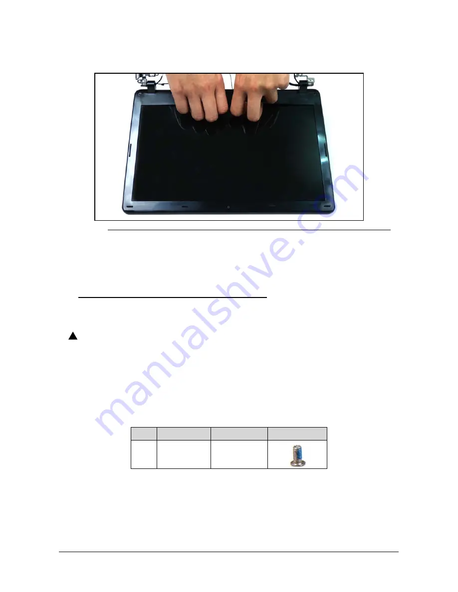
LCD Bezel Installation
0
1. Align hinge side of bezel to LCD cover and press down until there is no gap between bezel
and LCD module.
CAUTION
:
!
Make sure cables do not get caught underneath bezel, it may cause damage to
cables.
2. Move along edges until bezel is secure to LCD cover.
3. Install and secure screws (B) to LCD cover. (
)
4. Install mylar screw covers (A). (
)
5. Install LCD Module.
ID
Size
Quantity
Screw Type
B
M2.0x4.0 Ni
2
Summary of Contents for Aspire ONE 722
Page 1: ...i Aspire One 722 SERVICE GUIDE ...
Page 10: ...x ...
Page 11: ...CHAPTER 1 Hardware Specifications ...
Page 14: ...1 4 ...
Page 51: ...CHAPTER 2 System Utilities ...
Page 78: ...2 28 System Utilities ...
Page 79: ...CHAPTER 3 Machine Maintenance Procedures ...
Page 82: ...3 4 ...
Page 125: ...CHAPTER 4 Troubleshooting ...
Page 157: ...CHAPTER 5 Jumper and Connector Locations ...
Page 165: ...CHAPTER 6 FRU Field Replaceable Unit List ...
Page 166: ...6 2 Exploded Diagrams 6 4 Main Assembly 6 4 LCD Assembly 6 6 FRU List 6 7 Screw List 6 15 ...
Page 180: ...6 16 FRU Field Replaceable Unit List ...
Page 181: ...CHAPTER 7 Model Definition and Configuration ...
Page 182: ...7 2 Aspire One 722 7 3 ...
Page 210: ...7 30 Model Definition and Configuration ...
Page 211: ...CHAPTER 8 Test Compatible Components ...
Page 212: ...8 2 Microsoft Windows 7 Environment Test 8 4 Aspire One 722 8 4 ...
Page 219: ...CHAPTER 9 Online Support Information ...
Page 220: ...9 2 Introduction 9 3 ...
Page 222: ...9 4 Online Support Information ...