58
Chapter 3
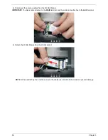
4.
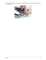
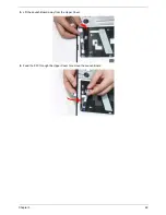
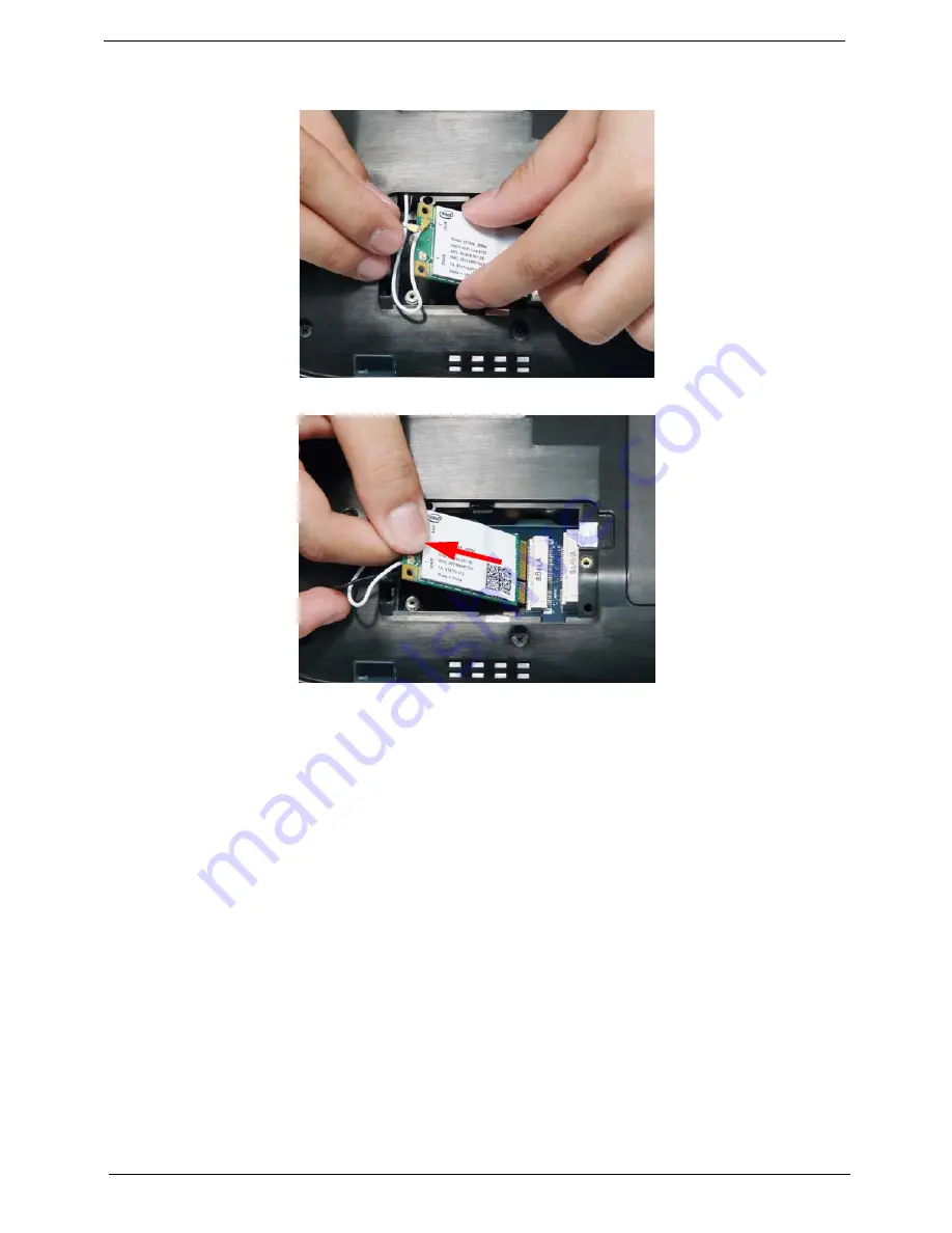
Disconnect the antenna cables from the WLAN Module.
IMPORTANT:
The black cable attaches to the
MAIN
terminal and the white cable attaches to the
AUX
terminal.
5.
Detach the WLAN Module from the WLAN socket.
NOTE:
When reattaching the antennas, ensure the cables are tucked into the chassis to prevent damage.
Summary of Contents for Aspire 5935 Series
Page 6: ...VI ...
Page 10: ...X Table of Contents ...
Page 14: ...4 Chapter 1 System Block Diagram ...
Page 47: ...Chapter 2 37 ...
Page 54: ...44 Chapter 2 ...
Page 83: ...Chapter 3 73 5 Disconnect the cable from the Power Saving Board as shown ...
Page 88: ...78 Chapter 3 8 Remove the FInger Print Reader from the bracket as shown ...
Page 98: ...88 Chapter 3 4 Lift the right side Saddle clear of the Lower Cover as shown ...
Page 102: ...92 Chapter 3 5 Disconnect the cable from the Bluetooth Module ...
Page 109: ...Chapter 3 99 5 Using both hands lift the Thermal Module clear of the Mainboard ...
Page 161: ...Chapter 5 151 LS 5011P LCD Backlight Board Item Description JP1 Backlight on off Connector ...
Page 164: ...154 Chapter 5 LS 5014P VR Board Item Description SW1 VR SWITCH ...
Page 165: ...Chapter 5 155 LS 5015P Finger printer Board Item Description U2 LTT SS801U 13_LGA28 ...
Page 170: ...160 Chapter 5 LS 501AP HDMI Board Item Description U1 CH7318A BF TR_QFN48_7X7 ...
Page 183: ...Chapter 6 173 ...
Page 212: ...Appendix A 202 ...
Page 218: ...208 Appendix B ...
Page 220: ...210 Appendix C ...
Page 224: ...214 ...


