


150
Chapter 4
Power On Issue
If the system doesn’t power on, perform the following actions one at a time to correct the problem. Do not
replace non-defective FRUs:
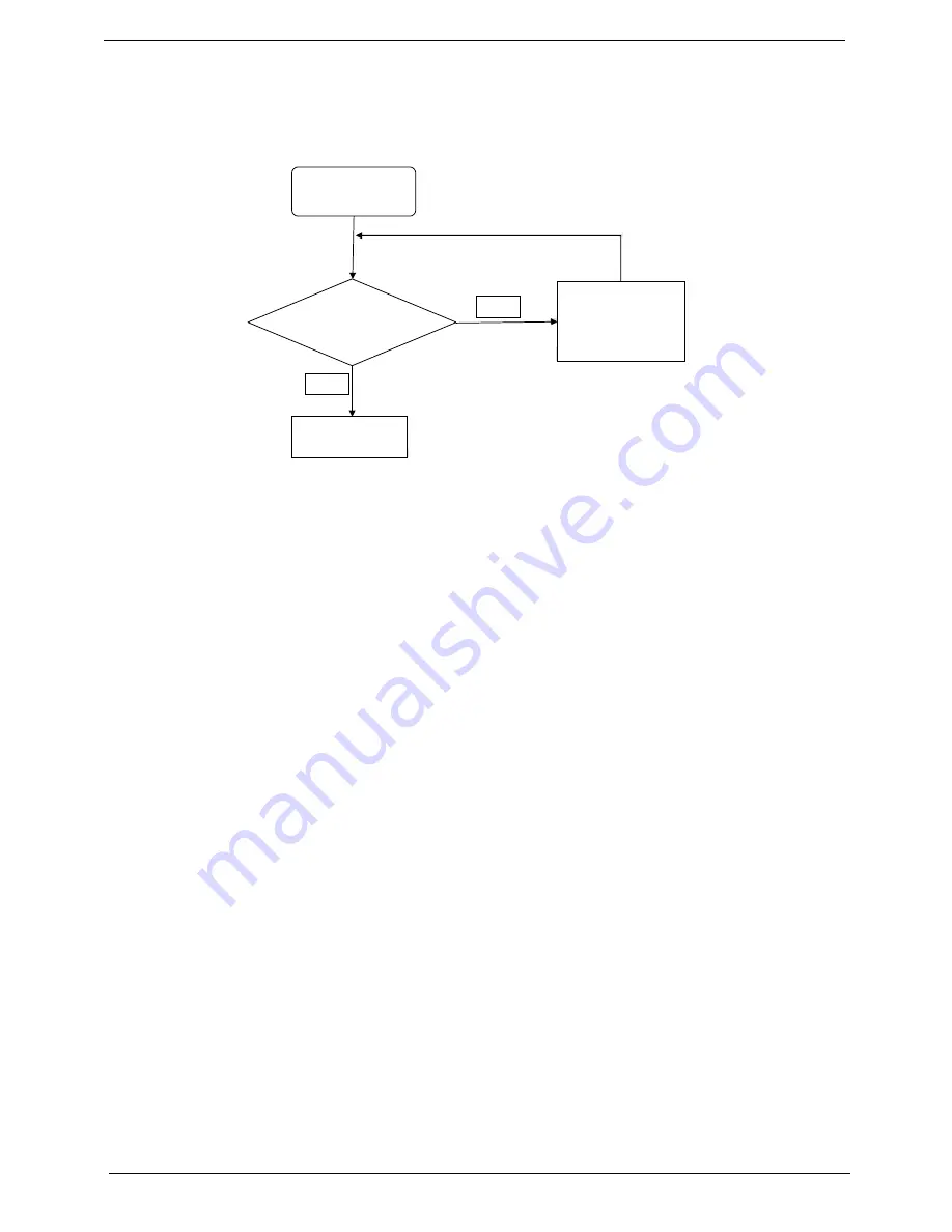
Computer Shuts down Intermittently
If the system powers off at intervals, perform the following actions one at a time to correct the problem.
1.
Check the power cable is properly connected to the computer and the electrical outlet.
2.
Remove any extension cables between the computer and the outlet.
3.
Remove any surge protectors between the computer and the electrical outlet. Plug the computer directly
into a known good electrical outlet.
4.
Remove all external and non-essential hardware connected to the computer that are not necessary to
boot the computer to the failure point.
5.
Remove any recently installed software.
6.
If the Issue is still not resolved, see “Online Support Information” on page 219.
Check
AC/Battery
Swap AC/Battery
try
NG
OK
Swap M/B
Start
Summary of Contents for ASPIRE 5625
Page 6: ...VI ...
Page 10: ...X Table of Contents ...
Page 42: ...32 Chapter 1 ...
Page 67: ...Chapter 3 57 4 Lift the base door out and away ...
Page 72: ...62 Chapter 3 5 Pull the WLAN module out and away ...
Page 86: ...76 Chapter 3 4 Unlock and disconnect the switch board FFC ...
Page 88: ...78 Chapter 3 4 Lift the power board away ...
Page 93: ...Chapter 3 83 14 Lift the LCD module out of the assembly ...
Page 111: ...Chapter 3 101 7 Disconnect the FPC cable ...
Page 114: ...104 Chapter 3 8 Remove the cables from the retention guides 9 Pry the antenna off the casing ...
Page 119: ...Chapter 3 109 7 Lay the cables along the retention guides ...
Page 134: ...124 Chapter 3 4 Connect and lock the USB card FFC to the mainboard ...
Page 136: ...126 Chapter 3 4 Connect the Bluetooth module cable to the main board ...
Page 146: ...136 Chapter 3 7 Connect and lock the button board FFC ...
Page 152: ...142 Chapter 3 4 Grasp the tab and slide the HDD firmly into the docking connector ...
Page 154: ...144 Chapter 3 Replacing the ODD Module 1 Replace the ODD bezel 2 Replace the ODD bracket ...
Page 158: ...148 Chapter 3 ...
Page 178: ...168 Chapter 5 ...
Page 190: ...180 Chapter 6 ...
Page 227: ...Appendix B 217 Modem External USB Lite LSI modem LC MOD00 001 Part Description Part ...
Page 228: ...218 Appendix B ...
Page 230: ...220 ...
Page 233: ...223 Index ...


