


Chapter 3
63
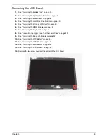
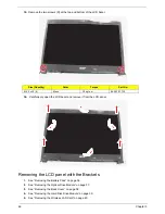
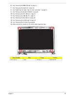
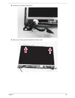
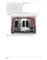
15.
Remove the four screws (A) from the left and right hinges.
16.
Carefully remove the LCD module from the base unit.
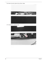
NOTE:
When connecting the cables back to the unit, please note that the cables should be routed well.
Size (Quantity)
Color
Torque
Part No.
M2.5 x L6 (4)
Black
3.0 kgf-cm
86.00E12.536
Summary of Contents for Aspire 4350
Page 6: ...VI ...
Page 26: ...18 Chapter 1 ...
Page 40: ...32 Chapter 2 ...
Page 84: ...76 Chapter 3 ...
Page 106: ...98 Chapter 5 ...
Page 108: ...100 Chapter 6 Exploded Diagram ...
Page 109: ...Chapter 6 101 ...
Page 121: ...Appendix A 113 Model Definition and Configuration Appendix A ...
Page 146: ...138 Appendix B ...
Page 148: ...140 Appendix C ...