


26
Chapter 2
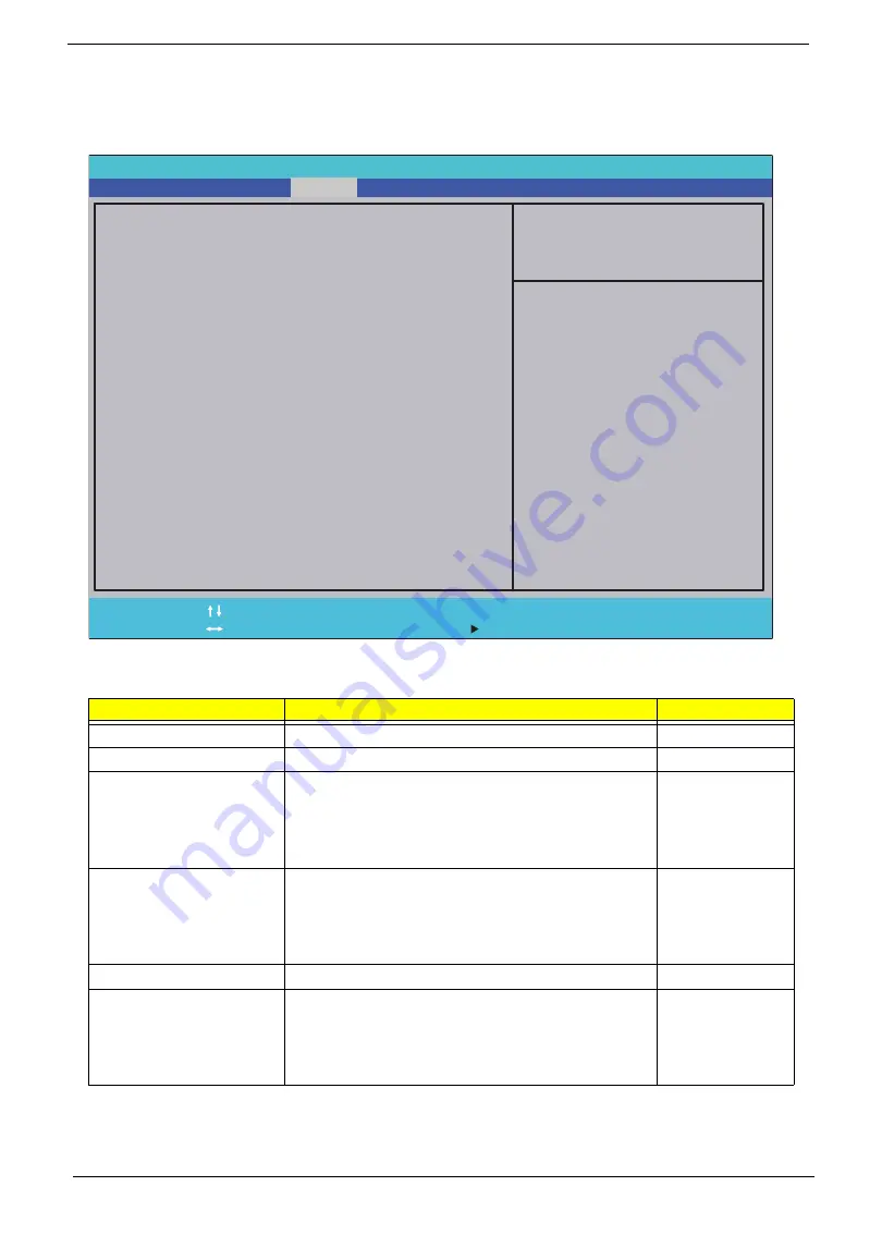
Security
The Security screen contains parameters that help safeguard and protect your computer from unauthorized
use.
The table below describes the parameters in this screen. Settings in
boldface
are the default and suggested
parameter settings.
NOTE:
When you are prompted to enter a password, you have three tries before the system halts. Don’t forget
your password. If you forget your password, you may have to return your notebook computer to your
dealer to reset it.
Parameter
Description
Option
Supervisor Password Is
Shows the setting of the Supervisor password
Clear
or Set
User Password Is
Shows the setting of the user password.
Clear
or Set
Set Supervisor Password
Press Enter to set the supervisor password. When
set, this password protects the BIOS Setup Utility
from unauthorized access. The user can not either
enter the Setup menu nor change the value of
parameters.
Set User Password
Press Enter to set the user password. When user
password is set, this password protects the BIOS
Setup Utility from unauthorized access. The user can
enter Setup menu only and does not have right to
change the value of parameters.
Set Hdd Password
Enter HDD password.
Power on password
Defines whether a password is required or not while
the events defined in this group happened. The
following sub-options are all requires the Supervisor
password for changes and should be grayed out if the
user password was used to enter setup.
Enabled
or
Disabled
InsydelH20 Setup Utility Rev. 3.5
F 1
E s c
H e l p
E x i t
S e l e c t I t e m
S e l e c t M e n u
C h a n g e Va l u e s
S e l e c t
S u b - M e n u
E n t e r
F 9
F 1 0
S e t u p D e f a u l t
S a v e a n d E x i t
Supervisor Password Is : Clear
User Password Is : Clear
HDD Password Is : Clear
Set Supervisor Password
Set User Password
Set Hdd Password
Power on password [Disabled]
F 5 / F 6
M a i n
B o o t
Exit
Security
Information
Item Specific Help
Install or Change the
password and the length
of password must be
greater than one word.
Summary of Contents for Aspire 1820PT Series
Page 6: ...vi ...
Page 10: ...x Table of Contents ...
Page 13: ...Chapter 1 3 System Block Diagram ...
Page 32: ...22 Chapter 1 ...
Page 48: ...38 Chapter 2 ...
Page 64: ...54 Chapter 3 4 Unlock the FPC 5 Remove the FPC and keyboard ...
Page 66: ...56 Chapter 3 4 Remove the hinge cap 5 Remove the hinge bezel ...
Page 70: ...60 Chapter 3 10 Pull the upper cover away ...
Page 94: ...84 Chapter 3 7 Pry up the bezel top edge and remove ...
Page 119: ...Chapter 3 109 7 Insert the stylus ...
Page 148: ...138 Chapter 3 2 Replace the HDD in the bay 3 Adhere the black tape 4 Replace the HDD FPC ...
Page 202: ...192 Appendix A ...
Page 212: ...202 ...
Page 215: ...205 ...
Page 216: ...206 ...


