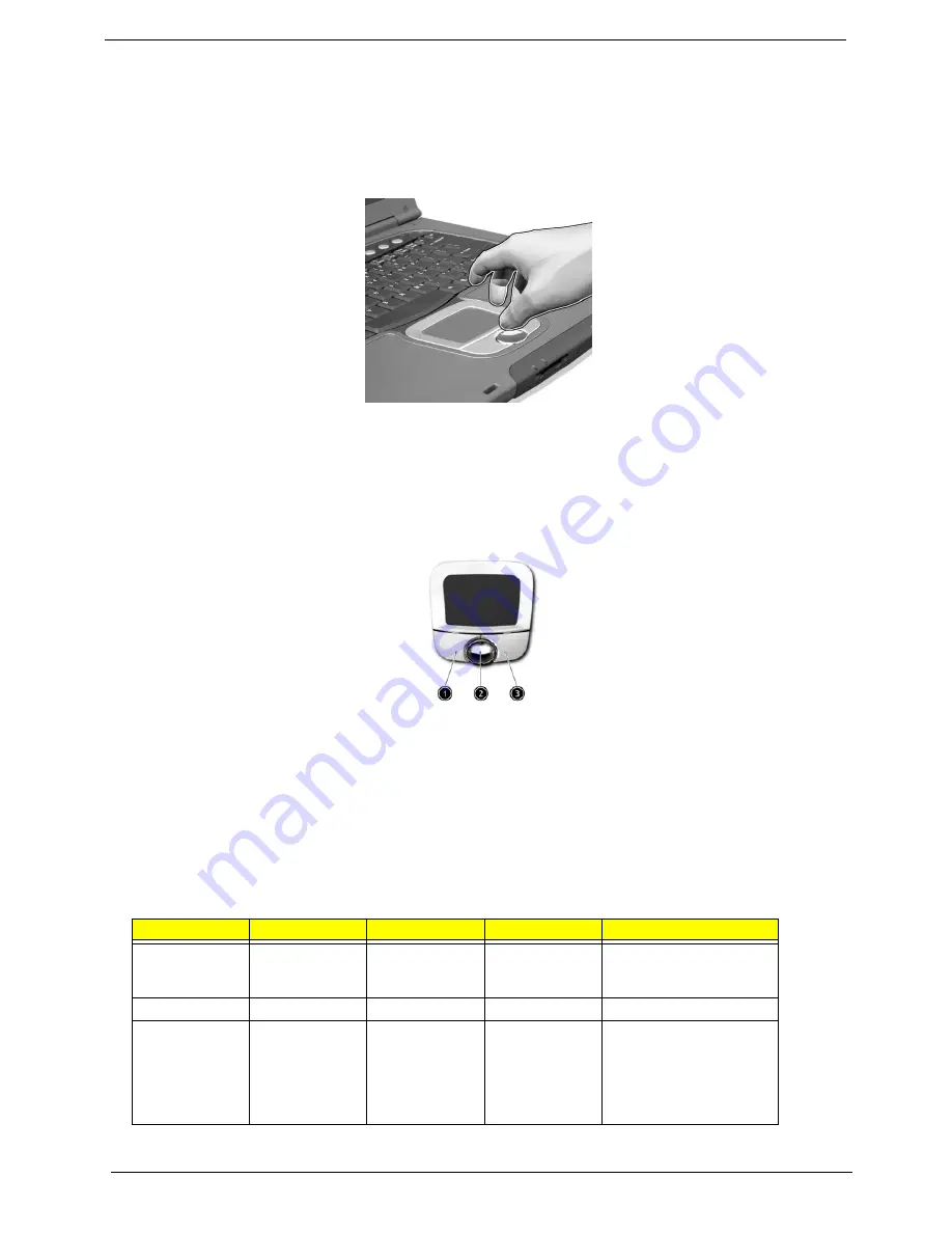
background image

20

Chapter 1

Touchpad

The built-in touchpad is a pointing device that senses movement on its surface. This means the cursor 
responds as you move your finger on the surface of the touchpad.  The central location on the palmrest 
provides optimal comfort and support.

NOTE: 

 If you are using an external USB mouse, you can press 

Fn-F7 

to disable the touchpad.

Touchpad Basics

The following items teache you how to use the touchpad:

T

Move your finger across the touchpad to move the cursor. 

T

Press the left (1) and right (3) buttons located on the edge of the touchpad to do selection and 
execution functions.  These two buttons are similar to the left and right buttons on a mouse. 
Tapping on the touchpad produces similar results.

T

Use the 4-way scroll (2) button (top/bottom/left/and right) to scrolla page up, down, left or right. 
This button mimics your cursor pressing on the vertical and horizontal scroll bars of Windows 
applications.

Function

Left Button

Right Button

Scroll Button

Tap

Execute

Click twice 
quickly

Tap twice (at the same 
speed as double-clicking 
the mouse button)

Select

Click once

Tap once

Drag

Click and hold, 
then use finger 
to drag the 
cursor on the 
touchpad

Tap twice (at the same 
speed as double-clicking 
a mouse button) then hold 
finger to the touchpad on 
the second tap to drag the 
cursor

Summary of Contents for Aspire 1450 Series

Page 1: ...pire 1450 Series Service Guide SERVICE CD PART NO VD A13V7 001 PRINTED IN TAIWAN Service guide files and updates are available on the ACER CSD web for more information please refer to http csd acer com tw ...

Page 2: ...II Revision History Please refer to the table below for the updates made on Aspire 1450 service guide Date Chapter Updates 2003 11 17 Chapter 4 Add POST codes ...

Page 3: ...pect to the contents hereof and specifically disclaims any warranties of merchantability or fitness for any particular purpose Any Acer Incorporated software described in this manual is sold or licensed as is Should the programs prove defective following their purchase the buyer and not Acer Incorporated its distributor or its dealer assumes the entire cost of all necessary servicing repair and an...

Page 4: ... bits and pieces of additional information related to the current topic WARNING Alerts you to any damage that might result from doing or not doing specific actions CAUTION Gives precautionary measures to avoid possible hardware or software problems IMPORTANT Reminds you to do specific actions relevant to the accomplishment of procedures ...

Page 5: ... NOT be covered in this generic service guide In such cases please contact your regional offices or the responsible personnel channel to provide you with further technical details 2 Please note WHEN ORDERING FRU PARTS that you should check the most up to date information available on your regional web or channel If for whatever reason a part number change is made it will not be noted in the printe...

Page 6: ...VI ...

Page 7: ...2 Info 33 Main 34 Advanced 36 Security 38 Boot 42 Exit 43 BIOS Flash Utility 44 System Diagnostic Diskette 44 Chpater 3 Machine Disassembly and Replacement 45 General Information 46 Before You Begin 46 Disassembly Procedure Flowchart 47 Removing the Battery Pack 50 Removing the Optical Module HDD Module Wireless Lan Card and LCD module 51 Removing the Optical Module 51 Removing the HDD Module 51 R...

Page 8: ...eck 63 Touchpad check 64 Power On Self Test POST Error Message 65 Index of Error Messages 66 POST Codes 68 Index of Symptom to FRU Error Message 72 Intermittent Problems 76 Undetermined Problems 77 Chapter 5 Jumper and Connector Locations 79 Top View 79 Bottom View 80 Chapter 6 FRU Field Replaceable Unit List 75 Exploded Diagram 76 Appendix A Model Definition and Configuration 86 Aspire 1450 Serie...

Page 9: ...s engine T Simultaneous LCD and CRT display support T S video for output to a television or display device that supports S video input T Automatic LCD dim feature that automatically decides the best settings for your display and conserves pwer T DualViewTM Multimedia T AC 97 stereo audio T Built in dual speakers T Built in microphone T High speed optical drive T Built in optical drive DVD ROM DVD ...

Page 10: ...Upgradeable memory I O Ports T One Card bus type II slot T One RJ 11 jack for 56Kbps fax modem T One RJ 45 jack for LAN T One DC in jack for AC adapter T One ECP EPP compliant 25 pin parallel port T One external 15 pin VGA port T One speaker headphone line out jack T One audio line in jack T One microphone in jack T Four USB 2 0 ports Disable middle port when docked with SPR T One IEEE 1394 port T...

Page 11: ... FAN 2 nd FAN P22 POWER IN North Bridge VIA KN400 P18 1394 CONN Slot0 1394 TSB43AB21 P23 P18 PCMCIA TI1410 SIO PC87393 P16 200 266 333 400MHZ DDR DIMM DDR DIMM P26 BIOS LPT Port P15 TV OUT P17 MINI PCI P24 FIR P16 AC 97 Link Secondary ATI M9 X AGP BUS EXT VGA MII CH7019 TV ENCODER LVDS P33 34 35 36 37 38 P14 VIN 2 5V 3 3V 3V_LAN 5V 5VPCU 5V 3V_MODEM 3V 5V 5V 3V 3VSUS 5VSUS 12V 3V 3V 3VSUS 5VSUS 5V...

Page 12: ...R164 R211 R155 R148 R124 R138 R160 R158 R297 R163 R157 L45 R139 R136 R142 R135 R125 L43 L44 R260 R259 R234 R289 R185 R183 R278 R281 R283 R215 R220 R208 R209 R270 R190 R221 R298 R288 R293 R256 R172 R296 R295 R268 R267 R187 R242 R224 R213 R216 R194 R196 R285 R287 R292 R284 R282 R263 R182 R210 R184 L51 R171 R207 R206 R286 R272 R265 R205 R204 R232 R262 R261 R252 R257 R280 R248 R225 R212 R264 R253 R275...

Page 13: ...2 PC94 PC81 PC87 PC79 PC102 PC92 C433 C432 PC96 PC111 PC91 PC90 C480 PC99 PC100 PC113 PC109 PC110 C447 C463 PC101 PC112 PC108 C420 PC82 C399 C400 C401 C395 C396 C397 C398 C394 C391 C392 C393 C708 C710 C389 C388 C387 C386 C390 C423 C424 C425 C385 C429 C731 C407 C406 C405 C428 C520 PC115 PC118 C783 C781 C784 C782 C785 C730 C402 C581 C582 C591 C587 C727 C726 C780 C777 C778 C779 C776 C725 C724 C771 C7...

Page 14: ...r button serves as a 4 way scroll button 5 Palmrest Comfortable support area for your hands when you use the computer 6 Keyboard Inputs data into your computer 7 Status indicators LEDs light emitting diode that turn on and off to show the status of the computer its functions and components 8 Microphone Internal microphone for sound recording 9 Launch keys Special keys for launching Internet browse...

Page 15: ...emory reader1 Reads cards from Smart Media Memory Stick MultiMedia and Secure Digital cards 3 4 in 1 status indicator1 Displays activity of 4 in 1 memory reader 4 Infrared port Interfaces with infrared devices e g infra red printer IR aware computer 5 Bluetooth button2 Starts Bluetooth functionality 6 Bluetooth indicator2 Indicates that optional Bluetooth is enabled 7 InviLink button3 Enables or d...

Page 16: ...4 devices 3 PC Card slot The slot supports a standard Type II CardBus PC Card 4 PC Card eject button Ejects the PC Card from the slot 5 Line in jack Accepts audio line in devices e g audio CD player stereo walkman 6 Microphone jack Accepts input from external microphone 7 Headphone Speaker Line out jack Connects to headphones or other line out audio devices speakers ...

Page 17: ...DVDs and writing to CD RWs DVD dual for reading both DVD RWs and writing to DVD RWs 2 Optical disc access indicator LED that indicates when an optical disc is being read or written 3 Optical drive eject button Press the eject button to remove a disc from the optical drive 4 Optical drive emergency eject hole Used to eject an optical disc when the computer is turned off 5 Power jack Connects to an ...

Page 18: ...10 100 based network 3 Parallel port Connects to a parallel device e g parallel printer 4 External display port Connects to a display device e g external monitor LCD projector 5 S video Connects t a television or display device with S video input 6 Security keylock Connects to a Kensington compatible computer security lock ...

Page 19: ...adding mini PCI cards 5 Hard disk protector Protects the hard disk from accidental bumps and vibration 6 Hard disk bay Houses the computer s hard disk secured by a screw 7 Memory compartment Houses th computer s main memory 8 Cooling fan Helps keep the computer cool Note Don t cover or obstruct the opening of the fan 9 Personal identification slot Insert a business card or similar sized indentific...

Page 20: ...ndicators are visible even when the display is closed Icon Function Description Caps lock Lights when Caps Lock is activated Num lock Lights when Num Lock is activated Media Activity Lights when the disc or optical drive is activated Power Lights gree when the power is on and orange when the computer is in standby mode Battery Lights orange when the battery is charging ...

Page 21: ... Lock Key Description Caps Lock When Caps Lock is on all alphabetic characters are typed in uppercase Toggle on and off by pressing the Caps Lock key on the left of the keyboard Num lock Fn F11 When Num Lock is on the embedded numeric keypad can be used Toggle on and off by pressing the Fn F11 keys simultaneously Scroll lock Fn F12 When Scroll Lock is on the screen moves one line up or down when y...

Page 22: ...fy the keyboard legend cursor control key symbols are not printed on the keys Desired Access Num Lock On Num Lock Off Number keys on embedded keypad Type numbers in a normal manner Cursor control keys on embedded keypad Hold j while using cursor control keys Hold Fn while using cursor control keys Main keyboard keys Hold Fn while typing letters on embedded keypad Type the letters in a normal manne...

Page 23: ...s logo key Start button Combinations with this key perform special functions Below are a few examples Tab Activates next taskbar button E Explores My Computer F Finds Document M Minimizes All j Windows logo key M Undoes Minimize All R Displays the Run dialog box Application key Opens a context menu same as a right click ...

Page 24: ...ility Fn F3 Power management scheme toggle Switches the power management scheme used by the computer function available if supported by operating system Fn F4 Sleep Puts the computer in Sleep mode Fn F5 Display toggle Switches display output between the display screen external monitor if connected and both the display screen and external monitor Fn F6 Screen blank Turns the display screen backligh...

Page 25: ...Chapter 1 17 Fn y Volume down Decreases the speaker volume Fn x Brightness up Increases the screen brightness Fn z Brightness down Decreases the screen brightness Hot Key Icon Function Description ...

Page 26: ...e steps below 1 Click on Start Control Panel 2 Double click on Regional and Language Options 3 Click on the Language tab and click on Details 4 Verify that the keyboard layout used for En English United States is set to United States International If not select and click on ADD then select United States International and click on OK 5 Click on OK To type the Euro symbol 1 Locate the Euro symbol on...

Page 27: ...n button works for model with 802 11b wireless LAN only E mail Detection Click right button at the Launch Manager icon on the taskbar and click on E mail Detection In this dialog box you have the option to enable disable mail checking set the time interval for mail checking etc If you already have an email account you can fill in User Name Password and POP3 Server in the dialog box The POP3 Server...

Page 28: ...touchpad to do selection and execution functions These two buttons are similar to the left and right buttons on a mouse Tapping on the touchpad produces similar results T Use the 4 way scroll 2 button top bottom left and right to scrolla page up down left or right This button mimics your cursor pressing on the vertical and horizontal scroll bars of Windows applications Function Left Button Right B...

Page 29: ...ouchpad is sensitive to finger movements Hence the lighter the touch the better the response Tapping too hard will not increase the touchpad s responsiveness Access context menu Click once Scroll Click and hold the button in the desired direction up down left right Function Left Button Right Button Scroll Button Tap ...

Page 30: ... Set by setup manual Second Level Cache Item Specification Cache controller Built in CPU Cache size 512KB 1st level cache control Always enabled 2st level cache control Always enabled Cache scheme control Fixed in write back System Memory Item Specification Memory controller AMD AthlonTM XP M built in Memory size 0MB no on board memory DIMM socket number 2 sockets Supports memory size per socket 1...

Page 31: ... 512MB 1536MB 1024MB 1024MB 2048MB LAN Interface Item Specification Chipset VT6103 Supports LAN protocol 10 100 Mbps LAN connector type RJ45 LAN connector location Rear panel Modem Interface Item Specification Chipset South bridge VIA VT8235 Data modem data baud rate bps 56K Supports modem protocol V 90 V 92 MDC Modem connector type RJ11 Modem connector location Rear panel Bluetooth MODEM Interfac...

Page 32: ...sks 1 1 for HGST 2 for TOSHIBA 2 Spindle speed RPM 4200 RPM 4200 RPM 4200 RPM Performance Specifications Buffer size 2048KB 2048KB 2048KB Interface ATA ATAPI 6 ATA 5 ATA ATAPI 6 ATA 5 ATA ATAPI 6 ATA 5 Max media transfer rate disk buffer Mbytes s 350 for HGST 317 for TOSHIBA 350 for HGST 317 for TOSHIBA 350 for HGST 317 for TOSHIBA Data transfer rate host buffer Mbytes s 100 MB Sec Ultra DMA mode ...

Page 33: ... Voltage 5 V 5 Operating DVD Combo Interface Item Specification Vendor model name QSI SBW 242 LiteOn LSC 24082K Performance Specification With CD Diskette With DVD Diskette Transfer rate Mbytes sec Sustained Max 3 6Mbytes sec for QSI Max 3 5Mbytes sec for LiteOn Sustained Max 10 56Mbytes sec for QSI Max 10 15Mbytes sec for LiteOn Data Buffer Capacity 2MB Interface IDE ATAPI 5 Applicable disc forma...

Page 34: ...n Video Interface Item Specification Chipset ATI M9 X Package Specifications Package Size 650 BGA 31mm x 31mm Supports ZV Zoomed Video port No Resolution Support Max 2D 3D resolution 2048x1536 Max color depth 16 7M Colors LVDS TMDS TV out 2048x1536 1600x1200 1024x768 Bus Specifications AGP bus support PCI bus support AGP 2X 3 3V 4X 1 5V PCI 2 2 Memory Type Samsung 4MBx32 DDR SDRAM VGA RAM Size 64M...

Page 35: ...tup IEEE 1394 Port Item Specification Chipset TI TSB43AB21 Interface USB Compliancy Level IEEE 1394 1 0 Number of IEEE 1394 port 1 Location Left side Connector type IEEE 1394 PCMCIA Port Item Specification PCMCIA controller TI PCI1410 Supports card type Type II Number of slots One type II Access location Left panel Supports ZV Zoomed Video port No ZV support Supports 32 bit CardBus Yes IRQ10 Syste...

Page 36: ...rk simultaneously by software specification Battery Item Specification Vendor model name Simplo Sanyo Battery Type Li ion Pack capacity 4400 Ah Cell voltage 3 7V cell Number of battery cell 8 Package configuration 4 cells in series 2 series in parallel Package voltage 14 8V LCD Item Vendor model name AU B150XG01 HITACHI TX38D81VC LG LP150X08 Mechanical Specifications LCD display area diagonal inch...

Page 37: ...stem Power Management ACPI mode Power Management Mech Off G3 All devices in the system are turned off completely Soft Off G2 S5 OS initiated shutdown All devices in the system are turned off completely Working G0 S0 Individual devices such as the CPU and hard disk may be power managed in this state Suspend to RAM S3 CPU set power down VGA Suspend PCMCIA Suspend Audio Power Down Hard Disk Power Dow...

Page 38: ...GA I O adress CF8 CFF PCI configuration register 000 00F DMA controller 1 IRQ Assignment Map Interrupt Channel Function Hardware IRQ00 System timer IRQ01 Keyboard IRQ02 Programmable interrupt controller IRQ03 IrDA Fast Infrared Port IRQ04 Communication port COM1 IRQ05 Winbond SD controller IRQ06 Standard floppy disk controller IRQ07 ECP printer port LPT1 IRQ08 CMOS RTC IRQ09 SCI IRQ used by ACPI b...

Page 39: ...reen Press m to enter setup Press F12 during POST to enter multi boot menu In this menu user can change boot device without entering BIOS SETUP Utility PhoenixBIOS Setup Utility Information Main Advanced Security Boot Exit CPU Type AMD Athlon XP M CPU Speed System BIOS Ver AS 1450_V1 00 VGA BIOS Ver AT M7 P V0 2 KBC Ver V1 00 Serial Number xxxxxxxxxxxxxxxxxxxxxx Asset Tag Number N A Product Name A...

Page 40: ... this item T Press while you are in any of the menu options to go to the Exit menu T In any menu you can load default settings by pressing t You can also press u to save any changes made and exit the BIOS Setup Utility NOTE You can change the value of a parameter if it is enclosed in square brackets Navigation keys for a particular menu are shown on the bottom of the screen Help for parameters are...

Page 41: ...U Speed System BIOS Ver AS 1450_V1 00 VGA BIOS Ver AT M7 P V0 2 KBC Ver V1 00 Serial Number xxxxxxxxxxxxxxxxxxxxxx Asset Tag Number N A Product Name Aspire 1450 Manufacturer Name Acer UUID xxxxxxxx xxxx xxxx xxxx xxxxxxxxxxxx F1 Help Select Item F5 F6 Change Values F9 Setup Defaults Esc Exit Select Menu Enter Select 4Sub Menu F10 Save and Exit IDE1 Model Name IDE1 Serial Number None None 22 Byte 3...

Page 42: ...ormation Main Advanced Security Boot Exit Item Specific Help System Time 00 00 00 System Date 10 15 2003 System Memory 640 KB Extended Memory 238 MB VGA Memory 16MB Quiet Boot Enabled Power on display Auto LCD Auto Dim Enabled Wakeup from LAN Disabled F12 Boot Menu Disabled Tab Shift Tab or Enter selects field F1 Help Select Item F5 F6 Change Values F9 Setup Defaults Esc Exit Select Menu Enter Sel...

Page 43: ...size 1MB Video Memory Shows the VGA memory size The default value is set to 32MB Option 32 64MB Quiet Boot Determines if Customer Logo will be displayed or not shows Summary Screen is disabled or enabled Enabled Customer Logo is displayed and Summary Screen is disabled Disabled Customer Logo is not displayed and Summary Screen is enabled Option Enabled or Disabled Power on display Auto During powe...

Page 44: ... if Mode is set to ECP or Bi directional This parameter is enabled only if Mode is set to ECP 378h 278h 3BCH Interrupt Sets the interrupt request of the parallel port IRQ7 IRQ5 DMA channel Sets a DMA channel for the printer to operate in ECP mode This parameter is enabled only if Mode is set to ECP DMA3 DMA1 PhoenixBIOS Setup Utility Information Main Advanced Security Boot Exit Item Specific Help ...

Page 45: ...ermines whether or not to disable the internal pointing device as the PS 2 mouse is connected Both or Auto Infrared Port FIR Enables disables or auto detects the infrared port Disabled EnabledDisabled Auto Parameter Description Options ...

Page 46: ... Password is Clear Supervisor Password is Clear Primary HardDisk Security Clear Set User Password Enter Set Supervisor Password Enter Password on boot Enabled Supervisor Password controls accesses of the whole setup utility It can be used to boot up when Password on boot is enabled F1 Help Select Item F5 F6 Change Values F9 Setup Defaults Esc Exit Select Menu Enter Select 4 Sub Menu F10 Save and E...

Page 47: ...ss u to save the changes and exit the BIOS Setup Utility Parameter Description Option User Password is Shows the setting of the uer password Clear or Set Supervisor Password is Shows the setting of the Supervisor password Clear or Set Primary Harddisk Security This feature is available to user when Supervisor password is set Password can be written on HDD only when Supervisor password or user pass...

Page 48: ... save the changes and exit the BIOS Setup Utility Changing a Password 1 Use the w and y keys to highlight the Set Supervisor Password parameter and press the e key The Set Password box appears 2 Type the current password in the Enter Current Password field and press e 3 Type a password in the Enter New Password field Retype the password in the Confirm New Password field 4 Press e After setting the...

Page 49: ...er the user presses u If the current password entered does not match the actual current password the screen will show you the Setup Warning If the new password and confirm new password strings do not match the screen will display the following message ...

Page 50: ...ity Boot Exit Item Specific Help Hard Drive Floppy Devices CD ROM Drive Keys used to view or configure devices Enter expnads or Collapses Devices with a or Ctrl Enter expnads all Shift 1 enables or disables a device and moves the device up or down n May move removable device between Hard Disk or Removable Disk d Remove a device that is not installed F1 Help Select Item F5 F6 Change Values F9 Setup...

Page 51: ... data to CMOS Load Setup Default Load default values for all SETUP item Discard Changes Load previous values from CMOS for all SETUP items Save Changes Save Setup Data to CMOS PhoenixBIOS Setup Utility Information Main Advanced Security Boot Exit Item Specific Help Exit Saving Changes Exit Discarding Changes Load Setup Defaults Discard Changes Save Changes Exit System Setup and save your changes t...

Page 52: ...h NOTE Please use the AC adaptor power supply when you run the Phlash utility If the battery pack does not contain enough power to finish BIOS flash you may not boot the system because the BIOS is not completely loaded Fellow the steps below to run the Phlash 1 Prepare a bootable diskette 2 Copy the Phlash utilities to the bootable diskette 3 Then boot the system from the bootable diskette The Phl...

Page 53: ...atic discharge T Small Philips screw driver T Philips screw driver T Flat head screwdriver T Plastic flat head screw driver T Hex screw driver T Tweezers NOTE The screws for the different components vary in size During the disassembly process group the screws with the corresponding components to avoid mismatch when putting back the components When you remove the stripe cover please be careful not ...

Page 54: ...g 1 Turn off the power to the system and all peripherals 2 Unplug the AC adapter and all power and signal cables from the system 3 Remove the battery pack NOTE Aspire 1450 series product uses mylar or tape to fasten the FFC FPC connectors cable you may need to tear the tape or mylar before you disconnect different FFC FPC connectors ...

Page 55: ... Start Battery HDD Door Middle Cover ODD Module HDD Module Hx2 Fx2 LCD Module Sx4 ODD Board ODD Bracket Keyboard Hx2 Mx3 Main Unit Assembly Front Bezel Logic Upper Assembly Sx19 Hx2 Ux3 Logic Lower Assembly Dimm Door Memory Hx2 Ox4 Function Key Board PCI Door Wireless LAN Card Hx2 Hx3 ODD Ax4 Hx1 Hx1 Main Board CPU Dimm HDD Bracket 4 in 1 Card Rearder Modem Bluetooth Combo Card Smart Card Reader T...

Page 56: ...I NI NYLOK F SCREW M2 0X5 I NI NYLOK G SCREW M2 5X3 I NI NYLOK H SCREW M2 5X4 0 B NI NYLOK I SCREW M2 5X4 I NYLOK J SCREW M2 5X5 0 I NI NYLOK K SCREW M2 5X5 5 P NI NYLOK LCD Module 6 LCD Cushions Jx6 LCD Bezel LCD Inverter LCD Assembly Hx4 LCD Panel LCD Brackets Hx4 LCD Coaxial Cable LCD Wireless Antenna Hx2 LCD Latch Kit Bracket Dx1 LCD Latch Kit Dx4 ...

Page 57: ... 7I NYLOK M SCREW M1 7X3 5 I BZN N SCREW M2X3 I BNI NYLOK O SCREW M2 0X5 0 I BNI NYLOK P SCREW M2 0X6 0 I NI NYLOK Q SCREW M2 5X2 I NI NYLOK R SCREW M2 5X4 I BNI S SCREW M2 5X7 T SCREW M3 0X3 5 U SCREW M2 5X5 BLACK Item Description ...

Page 58: ...50 Chapter 3 Removing the Battery Pack 1 Release the battery lock 2 Slide the battery latch then remove the battery ...

Page 59: ...atch 2 Remove the ODD module Removing the HDD Module 1 Remove the two screws holding the HDD cover 2 Remove the HDD cover 3 Remove the HDD module Removing the Wireless LAN Card 1 Remove the screw that secures the PCI door then remove the PCI door 2 Disconnect the right and the left wireless antenna 3 Pop out the wireless LAN card then remove it ...

Page 60: ...th the assistance of a plastic flat head screw driver 3 Disconnect the LCD cable then take out the cable from the upper case 4 Disconnect the left wireless LAN antenna line Then take out the antenna from the upper case with a tweezers 5 Unscrew the four screws holding the LCD hinges two on each side 6 Then remove the entire LCD module ...

Page 61: ...o screws as the picture shows 6 Turn over the keyboard Disconnect the keyboard FFC then remove the keyboard Separate the main unit into the logic upper and the logic lower assembly 1 Remove the three screws on the rear panel 2 Unscrew the 19 screws on the bottom panel 3 Detach the front bezel from the main unit 4 Remove the two screws Then take the right and the left antenna off the main unit 5 Di...

Page 62: ...crews holding the touchpad shielding and the touchpad board 3 Disconnect the touchpad FFC from the touchpad board 4 Remove the touchpad board 5 Remove the wireless and bluetooth button off the touchpad board 6 Remove the four screws that fasten the touchpad holder 7 Remove the touchpad off the logic upper assembly 8 Disconnect touchpad FFC ...

Page 63: ...ule 4 Disconnect the fan connector then remove the thermal module 5 Remove one screw that secures the main board as picture shows 6 Remove another screw that fastens the main board 7 Take out the bluetooth antenna 8 Disconnect the speaker set cable 9 To remove the main board from the lower case assembly first press the PCMCIA card button 10 Then take the main board off the lower case assembly 11 U...

Page 64: ...en remove the CPU 15 Pop out the memory then remove it 16 Unscrew the two screws that secure the modem bluetooth combo card Remove the modem bluetooth combo card then disconnect the connector 17 Disconnect the bluetooth antenna and the modem cable 18 Disconnect the smart card reader FPC 19 Unscrew the two screws holding the smart card reader then remove it ...

Page 65: ...e four screws that fasten the right and the left LCD brackets Then remove the right and the left LCD brackets 7 Tear off the electric conductive tape that fastens the LCD coaxial cable 8 Tear off another electric conductive tape that fastens the LCD coaxial cable 9 Disconnect the LCD coaxial cable 10 Detach the wireless antenna from the LCD panel 11 Remove the two screws holding the LCD latch kit ...

Page 66: ...58 Chapter 3 13 Unhook the spring 14 Remove the screw that fastens the LCD latch kit 15 Then remove the LCD latch kit ...

Page 67: ...cal Drive Module 1 Remove the two screws holding the ODD bracket 2 Remove another screw as the picture shows 3 Then remove the last two screws on the back side of the ODD module 4 Slide the ODD from the ODD bracket 5 Then remove the optical bracket 6 In order to open the ODD use an uncurved pin to press the emergency eject hole 7 Remove the three screws that fasten the ODD door 8 Then detach the O...

Page 68: ...60 Chapter 3 ...

Page 69: ...ed and secured there are no obvious shorts or opens there are no obviously burned or heated components all components appear normal 5 Use the following table with the verified symptom to determine which page to go to Symptoms Verified Go To Power failure The power indicator does not go on or stay on Power System Check on page 63 POST does not complete No beep or error codes are indicated Power On ...

Page 70: ...ached to it The label can cause damage to the drive or can cause the drive to fail Do the following to select the test device 1 Boot from the diagnostics diskette and start the diagnostics program refer to System Diagnostic Diskette on page 44 2 See if CD ROM Test is passed when the program runs to CD ROM Test 3 Follow the instructions in the message window If an error occurs reconnect the connect...

Page 71: ...he test items 4 Follow the instructions in the message window NOTE Make sure that the DIMM is fully installed into the connector A loose connection can cause an error Power System Check To verify the symptom of the problem power on the computer using each of the following power sources 1 Remove the battery pack 2 Connect the power adapter and check that power is supplied 3 Disconnect the power ada...

Page 72: ... light up replace the battery pack If the charge indicator still does not light up replace the DC DC charger board Touchpad check If the touchpad doesn t work do the following actions one at a time to correct the problem Do not replace a non defective FRU 1 After rebooting run Tracking Pad PS2 Mode Driver For example run Syn touch driver 2 Run utility with the PS 2 mouse function and check if the ...

Page 73: ...ext possible FRU to be replaced when servicing a computer If the symptom is not listed see Undetermined Problems on page 77 The following lists the error messages that the BIOS displays on the screen and the error symptoms classified by function NOTE Most of the error messages occur during POST Some of them display information about a hardware device e g the amount of memory installed Others may i...

Page 74: ...n reboot system Real time clock error RTC battery Run BIOS Setup Utility to reconfigure system time then reboot system Main board Previous boot incomplete Default configuration used Load Default Settings in BIOS Setup Utility RTC batter Main baord Invalid System Configuration Data Load Default Settings in BIOS Setup Utility Main board Operating system not found Enter Setup and see if fixed disk an...

Page 75: ...r on indicator turns on and LCD is blank Power source battery pack and power adapter See Power System Check on page 63 Reconnect the LCD connector Hard disk drive LCD cable LCD inverter LCD Main board Power on indicator turns on and LCD is blank But you can see POST on an external CRT Reconnect the LCD connectors LCD cable LCD inverter LCD Main board Power on indicator turns on and a blinking curs...

Page 76: ...memory autosize 18h 8254 timer initialization 1Ah 8237 DMA controller initialization 1Ch Reset Programmable Interrupt Controller 20h 1 3 1 1 Test DRAM refresh 22h 1 3 1 3 Test 8742 Keyboard Controller 24h Set ES segment register to 4 GB 26h Enable A20 line 28h Autosize DRAM 29h Initialize POST Memory Manager 2Ah Clear 215 KB base RAM 2Ch 1 3 4 1 RAM failure on address line xxxx 2Eh 1 3 4 3 RAM fai...

Page 77: ... Enable external and CPU caches 69h Setup System Management Mode SMM area 6Ah Display external L2 cache size 6Bh Load custom defaults optional 6Ch Display shadow area message 6Eh Display possible high address for UMB recovery 70h Display error messages 72h Check for configuration errors 76h Check for keyboard errors 7Ch Set up hardware interrupt vectors 7Eh Initialize coprocessor if present 80h Di...

Page 78: ...key lock A4h Initialize Typematic rate A8h Erase F2 prompt AAh Scan for F2 key stroke ACh Enter SETUP AEh Clear Boot flag B0h Check for errors B2h POST done prepare to boot operating system B4h 1 One short beep before boot B5h Terminate QuietBoot optional B6h Check password optional B9h Prepare Boot BAh Initialize DMI parameters BBh Initialize PnP Option ROMs BCh Clear parity checkers BDh Display ...

Page 79: ...BIOS E8h Set Huge Segment E9h Initialize Multi Processor EAh Initialize OEM special code EBh Initialize PIC and DMA ECh Initialize Memory type EDh Initialize Memory size EEh Shadow Boot Block EFh System memory test F0h Initialize interrupt vectors F1h Initialize Run Time Clock F2h Initialize video F3h Initialize System Management Mode F4h 1 Output one beep before boot F5h Boot to Mini DOS F6h Clea...

Page 80: ... horizontal or vertical lines displayed Reconnect the LCD cable LCD cable LCD Main board Indicator Related Symptoms Symptom Error Action in Sequence Indicator incorrectly remains off or on but system runs correctly Main board HDD CD ROM active indicators cannot work HDD CD ROM drive Device driver Main board Power Related Symptoms Symptom Error Action in Sequence Power shuts down during operation P...

Page 81: ...le Main board Check BIOS revision System can power on but you hear two long beeps B B and the LCD is blank Reinsert DIMM DIMM Main board Speaker Related Symptoms Symptom Error Action in Sequence In Windows multimedia programs no sound comes from the computer OS volume control Audio driver Speaker Main board Internal speakers make noise or emit no sound Speaker Main board Microphone cannot work Aud...

Page 82: ...d Setup defaults then reboot system Reconnect hard disk CD ROM drives FDD or other peripherals Main board External display does not work correctly Press Fn F5 LCD CRT Both display switching Keyboard Main board USB does not work correctly See System Diagnostic Diskette on page 44 Main board Print problems Enter BIOS Setup Utility to execute Load Default Settings then reboot the system Run printer s...

Page 83: ...roblems on page 77 Modem LAN Related Symptoms Symptom Error Action in Sequence Internal modem does not work correctly See System Diagnostic Diskette on page 44 Phone cable Driver Reconnect the Internal modem cable to the main board tightly Main board Internal LAN does not work correctly Lan cable Driver Main board ...

Page 84: ...tatic discharge or software errors FRU replacement should be considered only when a recurring problem exists When analyzing an intermittent problem do the following 1 Run the diagnostic test for the system board in loop mode at least 10 times 2 If no error is detected do not replace any FRU 3 If any error is detected replace the FRU Rerun the test to verify that there are no more errors ...

Page 85: ...the failure is operating correctly See Power System Check on page 63 1 Power off the computer 2 Visually check them for damage If any problems are found replace the FRU 3 Remove or disconnect all of the following devices T Non Acer devices T Printer mouse and other external devices T Battery pack T Hard disk drive T DIMM T PC Cards 4 Power on the computer 5 Determine if the problem has changed 6 I...

Page 86: ...78 Chapter 4 ...

Page 87: ...R276 R290 R150 R164 R211 R155 R148 R124 R138 R160 R158 R297 R163 R157 L45 R139 R136 R142 R135 R125 L43 L44 R260 R259 R234 R289 R185 R183 R278 R281 R283 R215 R220 R208 R209 R270 R190 R221 R298 R288 R293 R256 R172 R296 R295 R268 R267 R187 R242 R224 R213 R216 R194 R196 R285 R287 R292 R284 R282 R263 R182 R210 R184 L51 R171 R207 R206 R286 R272 R265 R205 R204 R232 R262 R261 R252 R257 R280 R248 R225 R212...

Page 88: ...C837 C833 C832 PC94 PC81 PC87 PC79 PC102 PC92 C433 C432 PC96 PC111 PC91 PC90 C480 PC99 PC100 PC113 PC109 PC110 C447 C463 PC101 PC112 PC108 C420 PC82 C399 C400 C401 C395 C396 C397 C398 C394 C391 C392 C393 C708 C710 C389 C388 C387 C386 C390 C423 C424 C425 C385 C429 C731 C407 C406 C405 C428 C520 PC115 PC118 C783 C781 C784 C782 C785 C730 C402 C581 C582 C591 C587 C727 C726 C780 C777 C778 C779 C776 C725...

Page 89: ...ROVIDERS your Acer office may have a DIFFERENT part number code from those given in the FRU list of this printed Service Guide You MUST use the local FRU list provided by your regional Acer office to order FRU parts for repair and service of customer machines NOTE To scrap or to return the defective parts you should follow the local government ordinance or regulations on how to dispose it properly...

Page 90: ...76 Chapter 5 Exploded Diagram ...

Page 91: ...YO LI ION 8CELL 4UR18650F 2 QC ZG1 4400mAH BT T2303 001 BATTERY SIMPLO LI ION 8CELL LI ION BATTERY PACK ZG14S2P 4400mAH BT T2306 001 Boards NS MODEM CARD Ambit T60M283 10 54 T29V7 001 NS MODEM BLUETOOTH COMBO BOARD AMBIT T60M665 00 54 T23V7 002 NS WIRELESS LAN BOARD 802 11g WNC KM8 1 54 A13V7 001 4 LAUNCH BOARD 55 T23V7 001 NS TOUCH PAD BOARD W CABLE 55 T23V7 002 Cables NS TOUCHPAD CABLE 50 T23V7 ...

Page 92: ...A03V7 005 NS POWER CORD DANISH 3 PIN 27 A03V7 006 NS POWER CORD AU 3 PIN 27 A03V7 008 Case Cover Bracket Assembly 3 MIDDLE COVER W NAME PLATE 42 A13V7 001 NS DIMM DOOR W SCREW 42 T23V7 002 10 LOWER CASE W O SPEAKER 60 A13V7 001 5 UPPER CASE W TOUCHPAD HOLDER 60 A13V7 002 8 I O BRACKET W MICROPHONE 33 A13V7 001 NS FRONT BEZEL FOR 4 IN 1 MODEL 42 T23V7 003 NS FRONT BEZEL FOR NON 4 IN 1 MODEL 42 T23V...

Page 93: ...S BLUETOOTH ANTENNA 50 T23V7 004 NS WIRELESS LAN ANTENNA Y CABLE 50 A13V7 001 NS WIRELESS LAN ANTENNA 50 A13V7 002 CPU NS AMD Athlon XP Barton 2200 1 66GHz 35W Low Voltage OPGA KC A2202 35W NS AMD Athlon XP Barton 2400 1 8GHz 35W Low Voltage OPGA KC A2402 35W NS AMD Athlon XP Barton 2500 1 8GHz 40W Low Voltage OPGA KC A2502 40W Picture No Partname And Description Part Number ...

Page 94: ...5 60G TOSHIBA NEPTUNE MK6021GAS KH 36004 001 HDD 2 5 60G FUJITSU V40 MHT2060AT 4 2KRPM F W 0021 KH 06006 003 NS HDD COVER 42 T23V7 010 NS HDD CASE 33 T23V7 004 Keyboard 2 KEYBOARD DARFON US INTERNATIONAL 99 N3482 41D 84 keys KB T2307 001 KEYBOARD DARFON SPANISH 99 N3482 40S 85 keys KB T2307 003 KEYBOARD DARFON BRAZILIAN PROTUGESE 99 N3482 406 85 Keys KB T2307 005 KEYBOARD DARFON UK NSK A640U 85KEY...

Page 95: ...1 LCD MODULE 15 TFT XGA AU B150XG01 V2 W ANTENNA 6M A13V7 011 LCD MODULE 15 TFT XGA LG W ANTENNA 6M A13V7 012 LCD MODULE 15 TFT XGA QDI QDI150XL06 01 W ANTENNA 6M A13V7 013 LCD MODULE 15 TFT XGA HITACHI TX38D81VC W ANTENNA 6M A13V7 014 NS LCD 15 TFT XGA AU B150XG01 V2 spwg B LK 15005 001 LCD 15 TFT XGA LG LP150X08 A3 spwg B LK 15008 007 LCD 15 TFT XGA QDI QD150XL06 01 SPWG B LK 15009 002 LCD 15 TF...

Page 96: ...DR333 HYS64D32020GDL 6 B INFINEON KN 25602 009 256MB DDR333 NT256D64SH8BAGM 6K NANYA KN 25603 009 256MB DDR333 MT8VDDT3264HDG 335C3 MICRON KN 25604 009 256MB DDR333 M470L3224DT0 CB300 SAMSUNG KN 2560B 005 256MB DDR333 W30256AAEPI652A ELPIDA KN 25609 002 512MB DDR333 HYS64D64020GBDL 6 B INFINEON KN 51202 007 512MB DDR333 NT512D64S8HBAFM 6K NANYA KN 51203 005 512MB DDR333 EBD52UC8AARA 6B ELPIDA KN 5...

Page 97: ...4X QSI SBW 242 FW UX16 KO 24X07 005 DVD CDRW COMBO DRIVE Lite On 24X LSC 24082K KO 02409 003 DVD DUAL 4X PIONEER DVR K12RA KU 00405 005 DVD DUAL 4X HLDS GWA 4040N KU 0040D 002 DVD CDRW COMBO DRIVE 24X KME UJDA750 KO 24X06 002 NS DVD ROM BEZEL FOR MKE 42 T23V7 006 DVD ROM BEZEL FOR QSI 42 T23V7 007 DVD CDRW COMBO BEZEL FOR QSI 42 T23V7 008 DVD CDRW COMBO BEZEL FOR Lite On 42 T29V7 003 DVD DUAL BEZE...

Page 98: ... 0 I NI NYLOK 86 A03V7 012 NS SCREW M2 0X3 5 I NI NYLOK 86 T23V7 005 NS SCREW M2 0X5 I NI NYLOK 86 T23V7 006 NS SCREW M2 5X3 I NI NYLOK 86 A03V7 010 NS SCREW M2 5X4 0 B NI NYLOK 86 T23V7 008 NS SCREW M2 5X4 I NYLOK 86 T23V7 009 NS SCREW M2 5X5 0 I NI NYLOK 86 T23V7 010 NS SCREW M2 5X5 5 P NI NYLOK 86 T23V7 011 NS SCREW M2 5X0 45 7I NYLOK 86 T23V7 012 NS SCREW M1 7X3 5 I BZN 86 A03V7 009 NS SCREW M...

Page 99: ...Chapter 5 85 ...

Page 100: ...ber CPU LCD Memory HDD GB ODD Card Reader Wireless LAN 1452LCi Athlon XP M 35W 2200 15 0 XGA 2x256M 40 24x Combo drive 4 in 1 11g 1454LMi Athlon XP M 40W 2500 15 0 XGA 2x256M 60 DVD Dual 4 in 1 11g Model Definition and Configuration Appendix A ...

Page 101: ...der Windows XP Home environment Refer to the following lists for components adapter cards and peripherals which have passed these tests Regarding configuration combination and test procedures please refer to the Aspire 1450 series Compatibility Test Report released by the Acer Mobile System Testing Department Test Compatible Components Appendix B ...

Page 102: ...P Cable LL5 1394 Port 1394 HDD IEEE 1394 Fire Wire USB 1 1 Combo Hard Drive 1394 External HDD CASE 1394 CCD APLUX C102T 1394 MO FUJITSU LIMITED MDF3130EE 1394 Cable P to P Pci Projector Panasonic PT_L757U Panasonic PT_L556EA USB 2 0 USB HUB Highspeed 4 Port USB HDD Billionton USB CD RW YAMAHA CD RW 70 USB C F Card Reader IOGEAR GFR201 USB 6 in 1 Card Reader SanDisk ImageMate 6 in 1 USB DVD CD RW P...

Page 103: ...CSI Adaptec SlimSCSI APA 1460D Card LAN Modem Card Xircom CreditCard Ethernet Modem 56K CEM56 100 ATA Card Adapter Flash Card SanDisk CF Card 128MB PQI Compact Flash Card PQI CF Card 128MB Zip Card ZIOMEGA USB ZIP 250 1394 CardBus Card IEEE 1394 CardBus Card DV Megician UPMOST Wireless LAN Card CISCO AIRONET 350 SERIES AIR PCM350 Quanta Wireless LAN Card WL 211F Wireless Card Bus Card BUFFALD WLI ...

Page 104: ...B C300 USB HDD HD 530 Tested to comply with FCC Standards USB CD ROM YAMAHA CD RW 70 USB Printer HP DiskJet 3425 Colour inKlet printer HP DeskJet 840C HP deskject 450 Canon BJC 3000 USB FDD Acer USB FDD YD 8U10 Teac USB FDD Logitec USB FDD USB Memory USB DRIVE 128MB Panasonic SUPER DISK LKRF235U USB LAN Billionton USB 10 100 FastEthernet BUFFALO USB 10 100M Ethernet LUX TX USB Zip IOMEGA USB ZIP 1...

Page 105: ... NEC Earphone e STEREO DYNAMIC HEADPHONES E 750 Pro 2 DYNAMIC HEADPHONES PH B333G Panasonic Stereo Headphones RP H1245 DELL harman kardon Microphone AIWA Mini Microphone Condenser MIC EM 420T Audio Jack JS 100 Jazz 3D Speaker SONY Earphone MDR CD60 Microsoft microphone Microphone Condenser Microphone Dynamic Microphone Item Specifications ...

Page 106: ...92 Appendix B ...

Page 107: ...sktop and Server models including T Service guides for all models T User s manuals T Training materials T Bios updates T Software utilities T Spare parts lists T TABs Technical Announcement Bulletin For these purposes we have included an Acrobat File to facilitate the problem free downloading of our technical material Also contained on this website are T Detailed information on Acer s Internationa...

Page 108: ...94 Appendix C ...

Page 109: ... voltage 22 package 22 type 22 D DIMM 22 Combinations 23 external 51 package 22 removing 51 Speed 22 voltage 22 Disassembly Battery Pack 48 CD ROM DVD ROM Module 53 Floppy Disk Drive 57 Procedure Flowchart 47 Display 3 E Error Symptom to Spare Part Index 65 External CD ROM Drive Check 62 External Diskette Drive Check 62 F Features 1 Flash Utility 44 Floppy Disk removing the 57 FRU Field Replaceabl...

Page 110: ... 63 Battery Pack 64 Processor 22 R RMA 75 S Second Level Cache 22 System Block Diagram 3 Layout 4 System Diagnostic Diskette 44 System Memory 22 System Utilities 31 System Utility Diskette 44 T Test Compatible Components 87 Touchpad Check 64 Troubleshooting 61 U Undetermined Problems 77 USB 27 utility BIOS 31 V Video 26 W Windows 2000 Environment Test 88 ...

Page 111: ...Index 97 ...

Reviews: