Altos S205F / S200F User’s Manual
8
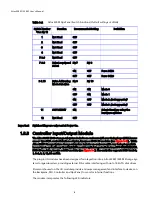
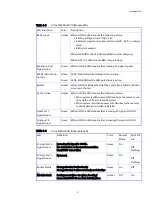
Table 1–2
Altos S200F Ops Panel Switch Functions (
Default settings at 2Gb/s)
Important
Switch settings are only read at Power On.
1.3.3 Controller Input/Output Module
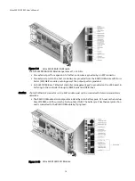
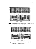
The Altos S200F JBOD storage subsystem includes an enclosure with rear facing bays which houses
one or two SATA control interface adaptor, known as JBOD I/O modules (see
While
Altos S205F Storage System storage subsystem includes an enclosure with rear facing bays which
houses two Loop Resiliency Circuit (LRC) I/O modules with integrated Infortrend IFT-1728RMN SATA
RAID I/O modules, known as RAID modules (see
). The controller supports RAID levels 0,
1, 0+1, 3, 5, 10, 30 and 50.
The plug-in I/O modules have been designed for integration into a Altos S205F / S200F Storage Sys-
tem storage subsystem, providing external FCAL cable interfacing with up to 16 SATA disk drives.
Processors housed on the I/O modules provide enclosure management and interface to devices on
the Backplane, PSU, Controller and Ops Panel, to monitor internal functions.
The module incorporates the following LED indicators:
Switch Number
*See Sw 11
Function
Recommended Setting
Definition
1
Not Used
OFF
2
Not Used
OFF
3
Not Used
OFF
4
Not Used
OFF
5 & 6
Not Used
OFF
7 & 8
Drive Loop Speed
Select
Sw 7
Sw 8
ON
OFF
Force 2Gb/s
OFF
OFF
Force 1Gb/s
9 & 10
Drive Addressing
Mode Selection
Sw 9
Sw 10
ON
ON
Mode 0
OFF
ON
Mode 1
ON
OFF
Mode 2
(not supported)
OFF
OFF
Mode 3
(not supported)
11
SOFT SELECT
ON
Selects functions using the
hardware switches
12
Not Used
OFF


