background image

Technical Information   


5.2 

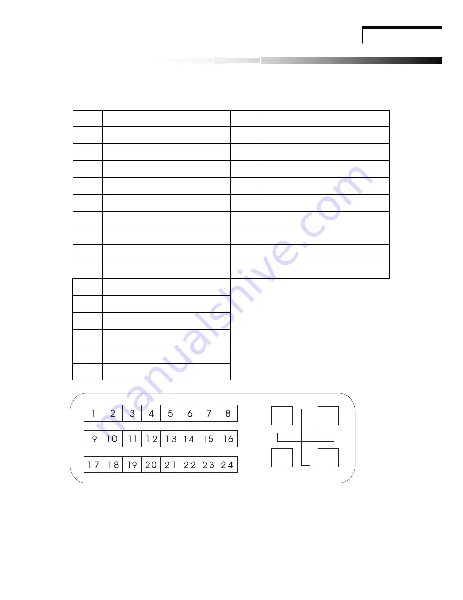
Signal connector pin assignment 

DVI Signal connector pin assignment 

PIN Signal 

(DVI) 

PIN Signal 

(DVI) 

TMDS    Data 2- 

16 

Hot Plug Detect 

TMDS  Data 2+ 

17 

TMDS  Data 0- 

TMDS  Data 2/4 shield 

18 

TMDS  Data 0+ 

TMDS  Data 4- 

19 

TMDS  Data 0/5 shield 

TMDS  Data 4+ 

20 

TMDS  Data 5- 

DDC  Clock 

21 

TMDS  Data 5+ 

DDC  Data 

22 

Clock shield 

8 Analog 

Vertical 

Synchronal 

23 Clock- 

TMDS    Data 1- 

24 

Analog B video Out 

10 

TMDS  Data 1+  


11 

TMDS  Data 1/3 shield 


12 

TMDS  Data 3- 


13 

TMDS  Data 3+ 


14 +5V 

Power 


15 Ground 


Signal connector 


14 

Summary of Contents for AL732

Page 1: ...onitor 3 1 Front Panel over view 3 3 2 Rear Panel over view 3 Chapter 4 Operation 4 1 Power ON OFF switch 4 4 2 Power indicator 4 4 3 Auto 4 4 4 Volume 4 4 5 Menu features 4 4 6 OSD menu 5 4 7 Self test pattern 11 4 8 Safety protection 11 4 9 Preset modes timing chart 12 Chapter 5 Technical information 5 1 Products Specifications 13 5 2 Signal Connector Pin Assignment 14 5 3 Troubleshooting 16 ...

Page 2: ...ference will not occur in a particular installation If this equipment does cause harmful interference to radio or television reception which can be determined by turning the equipment off and on the user is encouraged to try to correct the interference by one or more of the following measures 1 Reorient Relocate the receiving antenna 2 Increase the separation between the equipment and receiver 3 C...

Page 3: ...d never be blocked by placing the monitor on a bed sofa rug or other similar surface This monitor should not be placed in built in installation such as a bookcase unless proper ventilation is provided 6 Do not allow anything to rest on the power cord Do not locate this monitor where the cord will be abused by persons working on it 7 Never push objects of any kind into this monitor through cabinet ...

Page 4: ...VESA resolution standards Universal power supply TCO 99 compliant Microsoft Windows 9x 2000 XP compatible VESA Display Data Channel DDC 1 2B compatible 1 2 Checking List Please make sure the following items are included with your LCD monitor Your monitor AC Adapter AC power cord Signal cable Audio cable If any of these items are missing please contact with your dealer for technical support and cus...

Page 5: ...Chapter 2 nstallation Installation 2 ...

Page 6: ...3 2 Rear panel over view Over view of your monitor Chapter 3 O Ov ve er r v vi ie ew w o of f y yo ou ur r m mo on ni it to or r 3 1 Front panel over view 3 1 5 3 2 6 4 ...

Page 7: ...Chapter 4 OPERATION Direct Access Features O OP PE ER RA AT TI IO ON N D Di ir re ec ct t A Ac cc ce es ss s F Fe ea at tu ur re es s 4 ...

Page 8: ... release button Menu Analog RGB Digital RGB picture 1 auto adjust Press button auto adjust the display mode to its utmost performance according to VGA setting 2 brightness A A A A A A A A A A A A A A A A A A Adjust the overall image and background screen brightness 3 contrast Adjust the image brightness in relation to the background 4 h position To move the picture image horizontally left or right...

Page 9: ...o paper white user You can adjust the individual color intensity by yourself Increase or decrease red green or blue depending upon which is selected user red Increase or decrease red user green Increase or decrease green user blue Increase or decrease blue exit To exit the main menu audio 1 volume This features adjusts to decrease volume and to increase volume 2 base This features adjusts to decre...

Page 10: ...e the OSD image horizontally left or right 3 osd v position To move the OSD image vertically up or down 4 language You can choose one of the nine languages you need 5 exit To exit the main menu utilities 1 osd timeout You can select how long the monitor waits after the last adjust of the key to shut off the OSD menu The time setting choices are from 5 to 60 seconds 2 osd background You can select ...

Page 11: ...1 brightness Adjust the overall image and background screen brightness 2 contrast Adjust the image brightness in relation to the background 3 saturation Adjusts the color saturation of the screen image 4 hue Adjusts the color hue of the screen image 5 sharpness Adjusts the picture sharpness 6 scaling Adjusts the picture size full screen or 16 9 screen 7 exit To exit the main menu advanced 1 sharpn...

Page 12: ...ease red green or blue depending upon which is selected user red Increase or decrease red user green Increase or decrease green user blue Increase or decrease blue exit To exit the main menu audio 1 volume This features adjusts to decrease volume and to increase volume 2 base This features adjusts to decrease base and to increase base 3 treble This features adjusts to decrease treble and to increa...

Page 13: ...ose one of the nine languages you need 5 exit To exit the main menu utilities 1 osd timeout You can select how long the monitor waits after the last adjust of the key to shut off the OSD menu The time setting choices are from OFF to 60 seconds 2 osd background You can select opaque or translucent to change OSD background 3 source icon You can select on or off to display OSD icon 4 exit To exit the...

Page 14: ... test pattern When the computer s video signal is not reaching the monitor the monitor will display a self test pattern 4 8 Safety protection When frequency of video signal from computer s was out of range the monitor will protect by itself and a warning message of OSD will appear on the screen 11 ...

Page 15: ...rtical 720 400 31 47 kHz 70 Hz 640 480 31 47 kHz 60 Hz 640 480 37 86 kHz 72 8 Hz 640 480 37 5 kHz 75 Hz 800 600 37 88 kHz 60 3 Hz 800 600 48 08 kHz 72 2 Hz 800 600 46 87 kHz 75 Hz 1024 768 48 36 kHz 60 Hz 1024 768 56 48 kHz 70 1 Hz 1024 768 60 02 kHz 75 Hz 1280 1024 63 98 kHz 60 02 Hz 12 ...

Page 16: ... Luminance of white 250 cd m Bandwidth 135 MHz User Control 4 Key Sw OSD Functions Brightness contrast H position V position H Size phase Color auto Reset language OSD Exit View Angle Horizontal Vertical 160 degree 140 degree Adapter power input AC 100V to 240 V Power Consumption under 48 W Connector Signal D Sub 15Pin DVI 24Pin Safety EMI UL CUL TÜV GS CE FCC DOC CB VCCI TCO99 BSMI C Tick B Mark ...

Page 17: ...Data 2 17 TMDS Data 0 3 TMDS Data 2 4 shield 18 TMDS Data 0 4 TMDS Data 4 19 TMDS Data 0 5 shield 5 TMDS Data 4 20 TMDS Data 5 6 DDC Clock 21 TMDS Data 5 7 DDC Data 22 Clock shield 8 Analog Vertical Synchronal 23 Clock 9 TMDS Data 1 24 Analog B video Out 10 TMDS Data 1 11 TMDS Data 1 3 shield 12 TMDS Data 3 13 TMDS Data 3 14 5V Power 15 Ground Signal connector 14 ...

Page 18: ...l connector pin assignment PIN Signal D sub PIN Signal D sub 1 Red 9 5 VDC 2 Green 10 Ground 3 Blue 11 Ground 4 Ground 12 SDA For DDC 5 Self Test 13 H Sync 6 Red Ground 14 V Sync 7 Green Ground 15 SCL For DDC 8 Blue Ground Signal connector 15 ...

Page 19: ...ge or small Use the OSD controls to adjust Auto SETup The color are distorted Signal cable properly connected Use OSD controls to adjust the color control setting The image is too light or too dark Use OSD controls to adjust the brightness and contrast There is no sound or sound is low Check the sound cable connection Make sure the computer sound program is working Adjust the volume on sound setti...

Reviews: