Acer AL711 User Manual Download Page 5


5

Connecting the AC Power 


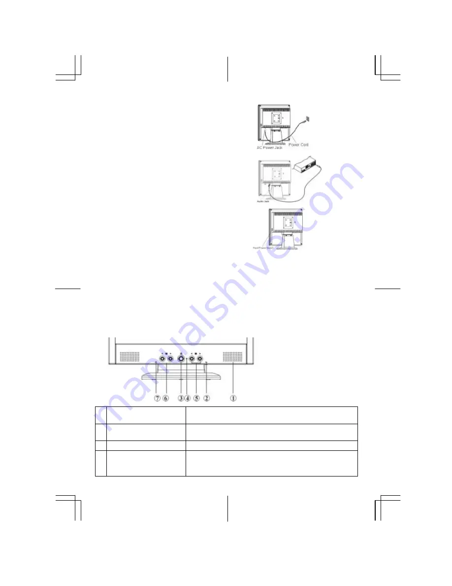
1.  Connect the power cord to the LCD Monitor.(See Fig. 1-6) 
2.  Connect the power cord to an AC power source.


Figure 1-6


Connecting the Audio Cable 
(For AL712/AL716)


1. 

Connect the audio cable to the " LINE OUT " jack on your 
PC's audio card or to the front panel's “AUDIO OUT” jack 
of your CD ROM drive. (See Fig. 1-7) 

2. 

Connect the other end of the audio cable to the LCD 
Monitor's " LINE IN " jack. 


Figure 1-7


Setting Up the LCD Monitor 

1.  Turn on the LCD monitor’s hard power switch, located on 

the back of the monitor 

2.  Turn on the LCD Monitor's  soft power switch, located on 

the bezel of the monitor. 


Figure 1-8


Power Management System


This LCD Monitor complies with the VESA DPMS (version 1.0) Power Management guidelines. The 
VESA DPMS provides four power saving modes through detecting a horizontal or vertical sync. signal.   
When the LCD Monitor is in power saving mode, the monitor screen will be blank and the power LED 
indicator will light yellow. 

Chapter 2 Display Controls 


User Controls 

A brief description and the location of all LCD Monitor function controls and indicators: 

Figure 2-1


Stereo Speakers  
(AL712/AL716) 

PC Audio Stereo output. 

Speaker Volume Control  
(AL712/AL716)


Increase Volume - Turn knob clockwise.   
Decrease Volume - Turn knob counter clockwise 

Soft Power Switch


Press the soft power switch to switch the monitor ON/OFF. 

DC Power-On Indicator


LED lights Green color --- Power is ON.   
LED lights Yellow --- Monitor is in "Power Saving Mode". 
LED is off --- Power is OFF. 

Summary of Contents for AL711

Page 1: ...s Theselimitsaredesignedtoprovidereasonableprotectionagainstharmfulinterferenceinaresidentialinstallation Thisequipment generates uses andcanradiateradiofrequencyenergy andifnotinstalledandusedinaccordancewiththeinstruction maycause harmfulinterferencetoradiocommunications However thereisnoguaranteethatinterferencewillnotoccurinaparticular installation Ifthisequipmentdoescauseharmfulinterferenceto...

Page 2: ...2 matériel brouilleur du Canada ...

Page 3: ... PC signal cable is frayed or damaged Liquid spilled into LCD Monitor or the monitor has been exposed to rain LCD Monitor or the case is damaged 7 A certified line is required to connect this device to a power outlet For a nominal current up to 6A and a device weight above 3 kg a line not lighter than H05VV F 3G 0 75 mm2 must be used Chapter 1 Installation Unpacking Before unpacking the LCD Monito...

Page 4: ...ing device please refer to Fig 1 3 The rear of this LCD display has four integrated 4 mm 0 7 pitches threaded nuts as well as four 5 mm access holes in the plastic covering as illustrated in Figure 1 4 These specifications meet the VESA Flat Panel Monitor Physical Mounting Interface Standard paragraphs 2 1 and 2 1 3 Figure 1 4 Connecting the Display 1 Power off your computer 2 Connect one end of t...

Page 5: ...stem This LCD Monitor complies with the VESA DPMS version 1 0 Power Management guidelines The VESA DPMS provides four power saving modes through detecting a horizontal or vertical sync signal When the LCD Monitor is in power saving mode the monitor screen will be blank and the power LED indicator will light yellow Chapter 2 Display Controls User Controls A brief description and the location of all...

Page 6: ...or s Display The monitor has four function control buttons to select among functions shown on OSD menu designed for easy user viewing environments OSD Function Menu ToaccessOSDMainmenu simplypressoneoftheFunctionSelect controlbuttons andthemenudiagramwillpopuponthescreenas shownonFig 2 2 ContinuepressingtheFunctionSelectbuttonstoscrollthroughtheentire menuitems thenpressAdjustment Controlbuttonsto...

Page 7: ... This function moves the OSD menu window horizontally OSD V Position This function moves the OSD menu window vertically Graph Text Because the H and V Frequencies of both 640 x 400 70Hz and 720 x 400 70Hz are the same this function let s you manually select either 640 x 400 graphics mode or 720 x 400 text mode Recall The recall function will return all adjusted parameters to factory preset values ...

Page 8: ...8 adjusted from the OSD menu Temperature ...

Page 9: ...sitive Negative 0 0 7 0 05 Vp Horizontal Frequency 24 80 KHz Vertical Frequency 56 75 Hz Control Power switch hard and soft types On Off switch with LED indicator OSD Brightness Contrast Horizontal Position Vertical Position Phase Clock Display Mode Setup OSD Format Digital Digital Digital Digital Digital Digital Use EEPROM to save settings in memory 20 characters x 9 rows Power Management Mode Po...

Page 10: ... Voltage Single phase 100 240VAC 50 60 Hz Input Current 1 2 A maximum Size and Weight Dimensions 374 W x 394 5 H x 204 D mm Net Weight 5 0 3 kg Gross Weight 7 0 3 kg Pin Assignment Signal Signal PIN Description PIN Description 1 5 6 10 11 15 1 2 3 4 5 6 7 8 Red Green Blue Digital GND Digital GND Red Rtn Green Rtn Blue Rtn 9 10 11 12 13 14 15 5V Hot Plug Detect NC SDA H Sync V Sync SCL For Digital ...

Page 11: ...11 ...

Page 12: ...nstable or unclear display whenever a new display mode or new VGA card is selected Attention This LCD Monitor Supports Multiple VGA Modes Refer to the Standard Timing Table for a listing of modes supported by this LCD Monitor PROBLEM Picture is unclear and unstable The picture is unclear and unstable please perform the following steps 1 Enter PC to Shut Down Windows status while you re in MS Windo...

Page 13: ...13 Also if the signal cable is not connected to LCD monitor at all or properly the monitor screen will display a message No Input Signal ...

Reviews: