15
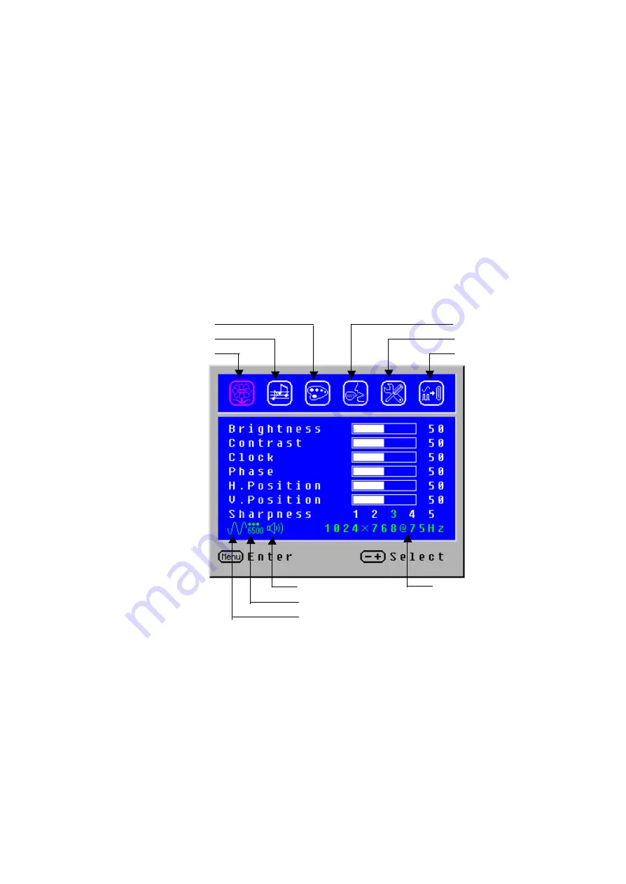
2.3 OSD Control
u
Press the “Menu” button to start the OSD feature.
u
Click the “+” or “-“ button to select the function to be adjusted.
u
Click the “Menu” button to access into the function to be adjusted.
u
Click the “+” or “-“ button to change the current setting of the function.
u
To exit the OSD menu or go back to the previous action by clicking
the “Auto/Exit” button. It will save the change automatically.
u
To repeat above steps for changing the setting of other functions.
2.4 OSD Menu Screen
u
The OSD disappears several seconds after you stop pressing the
buttons while performing an adjustment.
u
Any changes are automatically saved in the memory when the OSD
disappears. Turning off the power should be avoided while using the
menu.
u
Adjustments for clock, phase and positions are saved for each signal
timing. Except for these adjustments, all other adjustments have only
one setting which applies to all signal timings.
u
The color will change from white to pink while the function is selected.
Source Resolution & Frequency Status
Input Source Selection (optional)
Image Adjustment
Volume Adjustment
Audio Current Status
Language Selection
Settings
Input Source Status (Optional)
Color Temp. Status
Color Temp. Selection
Summary of Contents for AL1703
Page 2: ...2 ...
Page 3: ...3 ...
Page 4: ...4 ...
Page 5: ...5 ...
Page 6: ...6 ...
Page 24: ...24 Place Stand Assy Fasten 6 screws Insert Stand Cover Have the hook latched ...
Page 25: ...25 Troubleshooting 4 1 Abnormal Display Troubleshooting Chapter 4 2 ...
Page 26: ...26 ...
Page 27: ...27 4 2 Abnormal ON OFF LCD display Keyboard Troubleshooting ...
Page 28: ...28 4 3 Abnormal BIOS OSD Other Display Troubleshooting ...
Page 29: ...29 4 4 Audio Abnormal Troubleshooting ...
Page 31: ...31 5 2 Connector Location ...
Page 39: ...39 MAINBOAR D COVER Cover_pcb_ad D Sub Only 41A1799107 FFC COVER Cover FFC 41A1799102 ...
Page 40: ...40 ...
Page 41: ...41 Schematic Diagram Main Board Chapter 7 2 ...
Page 42: ...42 ...


