AccuMac AM1751 User Manual Download Page 6

AM1751 Secondary Reference PRT User’s Guide


Rev. 201609V3 

5/10

3  General Operations 

3.1  Connecting to the readout device 

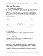
The AM1751 is equipped with a four-wire cable (see Figure 1). Four 
lead wires are used to cancel lead wire resistance. For best results, the 
readout device should be equipped to handle four-terminal resistors. 
The lead wires can be distinguished by insulation colors. Lead wire 
pairs attached to each end of the sensor are identified by red/black and 
white/blue insulation.  


3.2  Drive Current 

AccuMac recommends 1mA as drive current to ensure the best 
measurement. 


3.3  Stability of Readings 

To achieve the best accuracy, allow sufficient time for PRT to 
stabilize before taking the readings.  


3.4  Immersion Requirements 

Stem effect can cause measurement errors due to heat lost or gained 
by the sensing element through the thermometer stem. To minimize 
the error, appropriate immersion depths are required. A practical way 
to determine the minimum immersion depths is to change the depth 

Figure1 

Black 

Blue  

White 

Red 

Summary of Contents for AM1751

Page 1: ...Rev 201609V3 AM1751 Secondary Reference Platinum Resistance Thermometer User s Guide Please download the latest version at www accumac com...

Page 2: ...librations 3 2 Specifications 4 2 1 Specifications 4 3 General Operations 5 3 1 Connecting to the readout device 5 3 2 Drive Current 5 3 3 Stability of Readings 5 3 4 Immersion Requirements 5 3 5 Ther...

Page 3: ...live component 5 Follow all other safety guidelines listed in this user s guide Cautions Follow these guidelines to avoid possible damage to the instrument 1 Avoid mechanical shocks DO NOT drop or sla...

Page 4: ...e temperature or change of temperature It has wide applications for dry wells or temperature baths 1 2 Main Features High accuracy 0 015 C at 0 01 C Temperature range 200 C to 670 C Durable and shock...

Page 5: ...005 C Self heating 50 mW C Response Time 9 seconds for 63 response to step change in water moving at 3 feet per second Measurement Current 0 5 mA or 1 mA Sensor Length 32 mm Sensor Location 5 mm from...

Page 6: ...ach end of the sensor are identified by red black and white blue insulation 3 2 Drive Current AccuMac recommends 1mA as drive current to ensure the best measurement 3 3 Stability of Readings To achiev...

Page 7: ...has gone through an annealing process and stability test to minimize the thermal EMF which is caused by either impurities of sensing element or temperature differentials at lead wires connection poin...

Page 8: ...ssible b When shipping the PRT use protective box and other protective packaging materials to minimize mechanical shocks as much as possible c When using dry blocks make sure the well diameter is appr...

Page 9: ...service Be sure to have the model number and serial number of your PRT available 5 2 Problem Causes and Solutions a R0 Rtpw becomes higher significantly This is likely caused by mechanical shocks The...

Page 10: ...ty period begins on the date of the shipment Parts product repairs and services are warranted for 90 days The warranty extends only to the original buyer or end user customer of an AccuMac authorized...

Reviews: