


Quick Installation Guide
CheetaHub Power-3016G/3024G
6
7
Internal Switching Criteria
Network Bridging Function
Filtering, forwarding and learning
Switching Method
Store-and-forward
Address Table
2K entries
Queue Buffer
128K bytes
Filtering Rate
Line speed
Forwarding Rate
Line speed
Troubleshooting
Diagnosing Hub Indicators
The hub can be easily monitored through panel indicators to assist the network
manager in identifying problems. This section describes common problems you may
encounter and possible solutions.
Symptom: Power indicator does not light up (green) after power on.
Cause:
Defective power outlet, power cord, or internal power supply.
Solution: Check the power outlet by plugging in another device that is functioning
properly. Check the power cord with another device. If these measures fail
to resolve the problem, have the unit's power supply replaced by a qualified
Accton distributor.
Symptom: Link indicator does not light up after making a connection.
Cause:
Network interface (e.g., a network adapter card on the attached device),
network cable, or hub port is defective.
Solution: Verify that the hub and attached device are powered on. Be sure the cable is
plugged into both the hub and corresponding device. Verify that the proper
cable type is used and its length does not exceed specified limits. Check the
adapter on the attached device and cable connections for possible defects.
Replace the defective adapter or cable if necessary.
Power and Cooling Problems
If the Power indicator does not turn on when the power cord is plugged in, you may
have a problem with the power outlet, power cord, or internal power supply as
explained in the previous section. However, if the unit powers off after running for a
while, check for loose power connections, power losses or surges at the power
outlet, and verify that the fan on back of the unit is unobstructed and running prior to
shutdown. If you still cannot isolate the problem, then the internal power supply may
be defective. In this case, contact your Accton distributor for assistance.
Cabling and Adapters
If the Link indicator fails to light when you connect a device to the hub, check the
following items:
Be sure the twisted-pair cable is properly attached to the connected device and
the hub. Verify that the media connector snaps into place when attached.
See if your cable is functioning properly by using it for another port and attached
device that displays valid indications when connected to the network.
Check the length of each twisted-pair cable to be sure it does not exceed 100
meters (328 feet). If you have cascaded two Fast Ethernet hubs together, be sure
the interhub cabling is no longer than 5 meters (16 feet).
Verify that the workstation's adapter card is functioning properly by trying it in
another computer that has been successfully connected to the network.
Installation
Verify that all system components have been properly installed. If one or more
components appear to be malfunctioning (e.g., the power cord or network cabling),
test them in an alternate environment where you are sure that all the other
components are functioning properly.
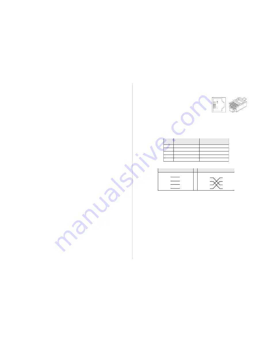
Port and Cable Assignments
RJ-45 Port Description
RJ-45 (MDI-X) station ports can be attached to any devices which use a standard
network interface (e.g., a workstation, server, bridge or router). RJ-45 (MDI) daisy-
chain ports can be cascaded to a station port on similar networking devices (e.g.,
another hub or switch). Use unshielded twisted-pair (UTP) or shielded twisted-pair
(STP) cable for RJ-45 connections: 100
Ω
Category 3, 4 or 5 cable for 10 Mbps
connections or 100
Ω
Category 5 cable for 100 Mbps connections. Also be sure that
the length of any twisted-pair connection does not exceed 100 meters (328 feet).
n
i
P
t
n
e
m
n
g
i
s
s
A
)
s
tr
o
P
n
o
it
a
t
S
(
t
n
e
m
n
g
i
s
s
A
)t
r
o
P
n
i
a
h
C
-
y
s
i
a
D
(
1
+
at
a
D
e
vi
e
c
e
R
t
u
p
nI
+
at
a
D
ti
m
s
n
a
r
T
t
u
pt
u
O
2
-
at
a
D
e
vi
e
c
e
R
t
u
p
nI
-
at
a
D
ti
m
s
n
a
r
T
t
u
pt
u
O
3
+
at
a
D
ti
m
s
n
a
r
T
t
u
pt
u
O
+
at
a
D
e
vi
e
c
e
R
t
u
p
nI
6
-
at
a
D
ti
m
s
n
a
r
T
t
u
pt
u
O
-
at
a
D
e
vi
e
c
e
R
t
u
p
nI
8
,
7
,
5
,
4
d
e
s
U
t
o
N
d
e
s
U
t
o
N
Schematics for both straight and crossover twisted-pair cable are shown below.
h
g
u
o
r
h
T
-t
h
g
i
a
rt
S
r
e
v
o
s
s
o
r
C
)
b
u
H
(
)r
et
p
a
d
A
(
)
b
u
H
(
)
b
u
H
(
+
D
R
I
1
+
D
T
O
1
+
D
R
I
1
+
D
R
I
1
-
D
R
I
2
-
D
T
O
2
-
D
R
I
2
-
D
R
I
2
+
D
T
O
3
+
D
R
I
3
+
D
T
O
3
+
D
T
O
3
-
D
T
O
6
-
D
R
I
6
-
D
T
O
6
-
D
T
O
6
EMI Certification
FCC Class A (USA)
Warning: This equipment generates, uses, and can radiate radio frequency energy
and, if not installed and used in accordance with the instruction manual, may cause
interference to radio communications. It has been tested and found to comply with
the limits for a Class A digital device pursuant to Subpart B of Part 15 of FCC Rules,
which are designed to provide reasonable protection against such interference when
operated in a commercial environment. Operation of this equipment in a residential
area is likely to cause interference, in which case the user, at his own expense, will
be required to take whatever measures are required to correct the interference.
Use Category 3, 4 or 5 unshielded or shielded twisted-pair cable for all 10Mbps
RJ-45 connection, and Category 5 unshielded or shielded twisted-pair for all
100Mbps RJ-45 connections.
Class A (Canada Department of Communications)
This digital apparatus does not exceed the Class A limits for radio noise emissions
from digital apparatus as set out in the interference-causing equipment standard
entitled "Digital Apparatus", ICES-003 of the Department of Communications.


