Entry module EVK hardware user guide
Page 21 of 30
2020-09-25
© 2020 by Acconeer
–
All rights reserved
Page 1: ...Entry module EVK hardware user guide Entry module EVK hardware user guide XE132...
Page 2: ...Entry module EVK hardware user guide Page 2 of 30 2020 by Acconeer All rights reserved 2020 09 25 Entry module EVK hardware user guide XE132 Author Acconeer Version 1 0 2020 08 31 Acconeer AB...
Page 3: ...3 The EVK Hardware 6 3 1 XE132 Evaluation Board 9 3 1 1 Overview 9 3 1 2 Power 10 3 1 3 Not Mounted Components 10 3 1 4 Electrical Schematics 11 3 1 5 Bill of Material 15 3 1 6 Component Placement Dra...
Page 4: ...CR It has leading edge patented sensor technology with pico second time resolution The A111 sets a new benchmark as far as power consumption and distance accuracy are concerned and it comes fully inte...
Page 5: ...nloaded at the same site 2 2 SW API Description The Acconeer SW comes with an API Application Programming Interface Acconeer provides several service oriented example and reference applications as wel...
Page 6: ...y module EVK hardware user guide Page 6 of 30 2020 by Acconeer All rights reserved 2020 09 25 3 The EVK Hardware In Figure 1 the block diagram of the XE132 is shown Figure 2 shows the XM132 block diag...
Page 7: ...neer All rights reserved XM132 USB1 Connector 5V Boot0 NRST Button DFU Button XE132 V_EXT 1 8 3 6V GPIO pin header USB VIN 0 Ohm Power pin header VIN_XM132 USB UART converter CP2105 SWD connector NRST...
Page 8: ...20 09 25 24MHz XTAL XM132 ENABLE INTERRUPT BOOT0 NRST SPI CTRL ENABLE INTERRUPT CTRL Power switch A111 PS_ENABLE STM32G071CBU6 Switched Power Regulator LC filter 1V8 Land Grid Array CPU 32 bit 64MHz C...
Page 9: ...It makes the interfaces from the XM132 module accessible for evaluation and debug It also enables flashing of the XM132 via USB UART or SW DP The XM132 Entry module is included in the XE132 Evaluatio...
Page 10: ...o measure only the current consumed by XM132 power should be supplied to XM132 via the pin VIN_XM132 in pin header J3 In this case R25 should be unmounted and S1 should be placed in position 3 3V This...
Page 11: ...Entry module EVK hardware user guide Page 11 of 30 2020 09 25 2020 by Acconeer All rights reserved 3 1 4 Electrical Schematics On the following pages please find the Electrical Schematics for XE132...
Page 12: ...Entry module EVK hardware user guide Page 12 of 30 2020 by Acconeer All rights reserved 2020 09 25...
Page 13: ...Entry module EVK hardware user guide Page 13 of 30 2020 09 25 2020 by Acconeer All rights reserved...
Page 14: ...Entry module EVK hardware user guide Page 14 of 30 2020 by Acconeer All rights reserved 2020 09 25...
Page 15: ...cro USB 2 0 B Receptacle STD 10118194 0001LF 1 Manufacturer Amphenol R23 Chip Resistor 0402 5 33R 1 33Ohm R2 Chip Resistor 0402 5 24K 1 24kOhm U2 TVS Diode 30kV SOT143 4 SP0503BAHTG 1 Manufacturer Lit...
Page 16: ...Entry module EVK hardware user guide Page 16 of 30 2020 by Acconeer All rights reserved 2020 09 25 3 1 6 Component Placement Drawing The component placement drawing of XE132 is found below Top Side...
Page 17: ...USB J1 USB is used as power supply for the XB132 as well as for flashing and communicating over UART USB is connected to the Silicon Labs chip CP2105 which converts the UART interfaces from XM132 into...
Page 18: ...nterface The pinout matches that of the Cortex 10 pin JTAG SWD Connector and is found in Table 4 Table 4 The pinout of J6 Pin Number Signal Pin Number Signal 1 VIN_XM132 2 SWD_IO 3 GND 4 SWD_CLK_BOOT0...
Page 19: ...ignal on XM132 In Table 6 the state of the buttons and the corresponding signal states are listed Table 6 The states of the buttons J4 and J5 Button Open default Closed J4 BOOT 0 BOOT0 1 J5 NRESET 1 N...
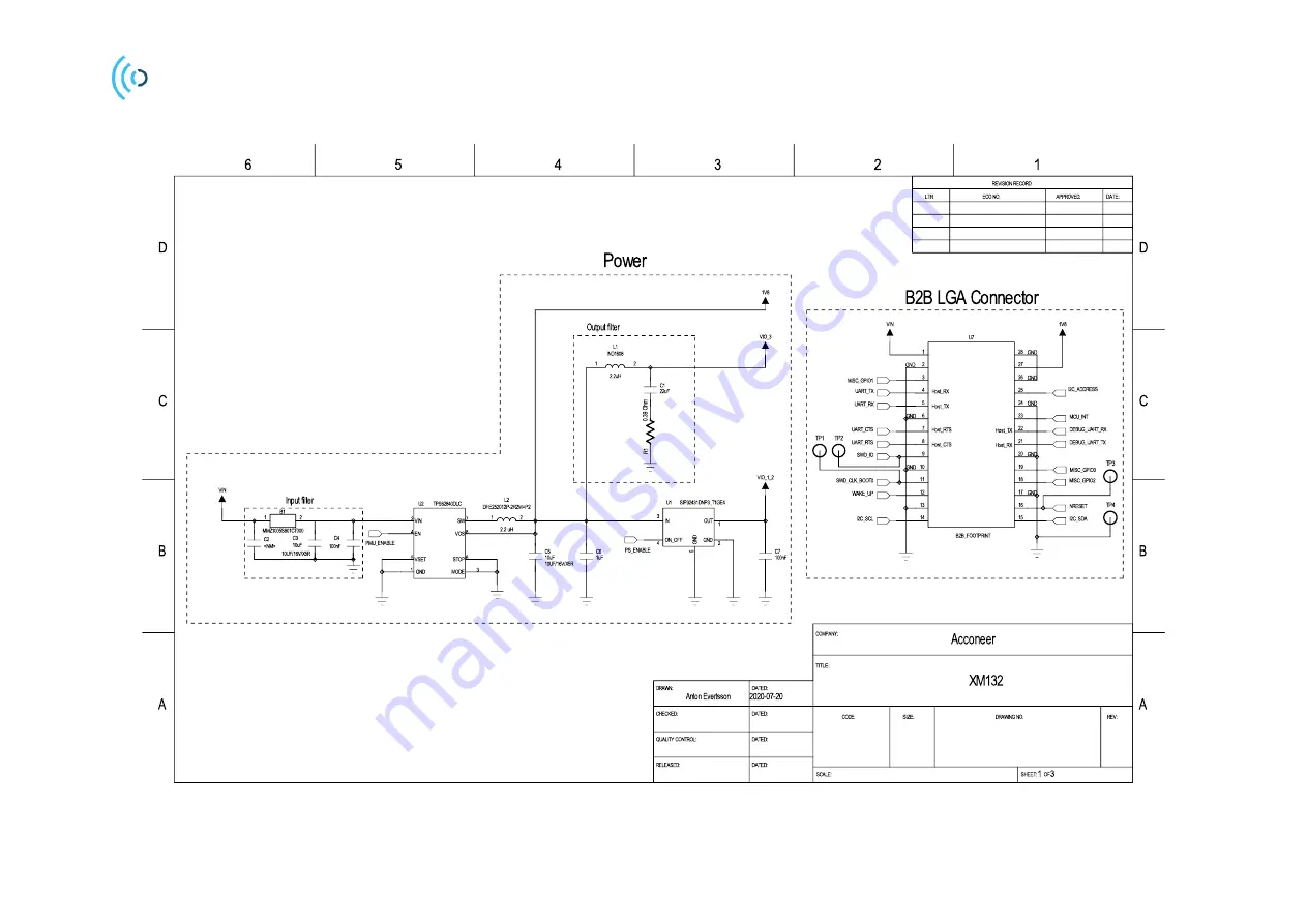
Page 20: ...Entry module EVK hardware user guide Page 20 of 30 2020 by Acconeer All rights reserved 2020 09 25 Electrical Schematics On the following pages please find the Electrical Schematics for XM132...
Page 21: ...Entry module EVK hardware user guide Page 21 of 30 2020 09 25 2020 by Acconeer All rights reserved...
Page 22: ...Entry module EVK hardware user guide Page 22 of 30 2020 by Acconeer All rights reserved 2020 09 25...
Page 23: ...Entry module EVK hardware user guide Page 23 of 30 2020 09 25 2020 by Acconeer All rights reserved...
Page 24: ...hip Resistor 0402 5 33R 1 33Ohm L1 IND1608 Inductors 2 2uH 20 500mA 1 2 2uH TDK MLZ1608N2R2LT000 L2 2520 2 2UH 20 40 125 C 1 2 2uH Abracon LLC ASMPH 1008 2R2M T Alternative Murata DFE252012P 2R2M P2 B...
Page 25: ...igure 3 XM132 top side 3 2 4 Land Grid Array Pinning In Table 8 the LGA pinning U7 is shown Table 8 The pinning of the XM132 Land Grid Array Pin Number Signal Comment 1 VIN 1 8 3 6V typical 3 3V 2 Gro...
Page 26: ...ll start the embedded boot loader 12 WAKE_UP Could be used by host to wake up XM132 MCU 13 Ground 14 I2C_SCL 15 I2C_SDA 16 NRESET Reset of XM132 MCU 17 Ground 18 MISC_GPIO2 19 MISC_GPIO0 20 Ground 21...
Page 27: ...2020 09 25 2020 by Acconeer All rights reserved 4 Safety 4 1 Electrostatic precautions Please take electrostatic precautions including using ground straps when using the EVK or any of its components...
Page 28: ...ory status it is the user s responsibility to ensure that any regulatory requirements applicable to any region are followed in the region the device is being used Regulatory Compliance for A111 The cu...
Page 29: ...Entry module EVK hardware user guide Page 29 of 30 2020 09 25 2020 by Acconeer All rights reserved 6 Revision History Date Revision Changes 2020 08 31 1 0 Original version...
Page 30: ...failure to meet such industry standard requirements Unless explicitly stated herein this document Acconeer has not performed any regulatory conformity test It is the user s responsibility to assure th...