


Sharp SmartPunch Pro Installation Manual
11
7. Final Steps
7.1 Main Unit & Finisher Firmware
Confirm that the main unit and finisher have the latest firmware installed. Firmware can be obtained by
contacting Sharp service.
7.2 Setting the Dip Switch
SmartPunch Pro unit is fitted with a dip-switch and the setting should be changed depending on the main
unit it is attached to. The dip-switch is located next to the firmware upload connector on the rear cover.
Set the dip-switch per the table below.
Dip Switch Setting
Main Unit
1
2
3
4
5
6
7
8
MX-M904, MX-M1054, MX-M1204
OFF
OFF
OFF
OFF
ON
ON
ON ON
MX-7500N,
MX-6500N
ON
ON
ON
ON
OFF
OFF OFF OFF
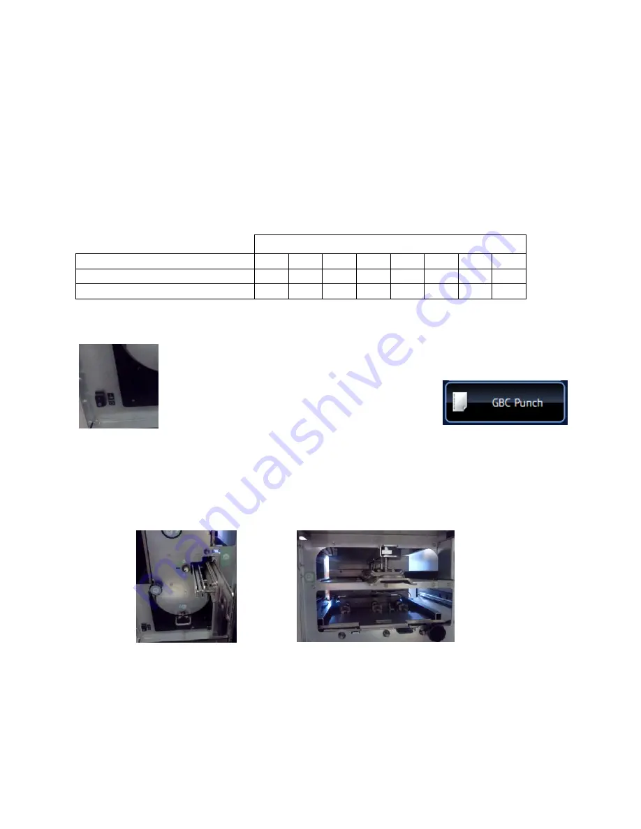
7.3 Enabling the Punch Icon
The power switch for the SmartPunch Pro can be found on the front frame on the
lower left corner (shown left). Turn the SmartPunch Pro on before the main unit.
The Punch icon (shown right) will appear automatically if
the connections are made correctly and the power is
cycled.
7.4 Functional Test
Functional test the SmartPunch Pro system
a) Check to ensure that the paper chip tray is securely in place.
b) Check to ensure that a die set is installed properly and that any extra die sets are securely stored in
the die storage area. The die is inserted as shown and should be pushed smoothly and firmly until it clicks
into place.
Inserting
the
die
Die
storage
area
c) Run a small test job in “Bypass” mode. Check to ensure that the job is not punched and bypasses
properly.
d) Run a small job with punch enabled. Check the punched holes of the job.
e) Run each die set to punch 100 sheets or until there is no oil residue around the holes.


