Acces I/O products DAQ-PACK Series User Manual Download Page 2


DAQ-PACK Series Modules User Guide 


Notice


The information in this document is provided for reference only. ACCES does not assume any liability arising 
out of the application or use of the information or products described herein. This document may contain or 
reference information and products protected by copyrights or patents and does not convey any license under 
the patent rights of ACCES, nor the rights of others. IBM PC, PC/XT, and PC/AT are registered trademarks of 
the International Business Machines Corporation. Copyright by ACCES I/O Products, Inc. 10623 Roselle Street, 
San Diego, CA 92121. All rights reserved. 
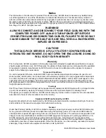
WARNING!!


ALWAYS CONNECT AND DISCONNECT YOUR FIELD CABLING WITH THE 

COMPUTER POWER OFF. ALWAYS TURN POWER OFF BEFORE 

CONNECTING AND DISCONNECTING CABLES, FAILURE TO DO SO MAY 

CAUSE DAMAGE TO THE DAQ-PACK AND WILL VOID ALL WARRANTIES, 

IMPLIED OR EXPRESSED. 


CAUTION!! 

THE DAQ-PACK SERIES IS A FULLY FACTORY CONFIGURED AND 

INTEGRATED INSTRUMENT, DO NOT OPEN THE ENCLOSURE, DOING SO 

WILL VOID YOUR WARRANTY 


Warranty


Prior to shipment, ACCES equipment is thoroughly inspected and tested to applicable specifications. However, 
should equipment failure occur, ACCES assures its customers that prompt service and support will be available. 
All equipment originally manufactured by ACCES which is found to be defective will be repaired or replaced 
subject to the following considerations. 

Terms and Conditions


If a unit is suspected of failure, contact ACCES' Customer Service department. Be prepared to give the unit 
model number, serial number, and a description of the failure symptom(s). We may suggest some simple tests 
to confirm the failure. We will assign a Return Material Authorization (RMA) number which must appear on the 
outer label of the return package. All units/components should be properly packed for handling and returned 
with freight prepaid to the ACCES designated Service Center, and will be returned to the customer's/user's site 
freight prepaid and invoiced. 

Coverage


First Three Years: Returned unit/part will be repaired and/or replaced at ACCES option with no charge for labor 
or parts not excluded by warranty. Warranty commences with equipment shipment. Following Years: 
Throughout your equipment's lifetime, ACCES stands ready to provide on-site or in-plant service at reasonable 
rates similar to those of other manufacturers in the industry. 
 

Equipment Not Manufactured by ACCES


Equipment provided but not manufactured by ACCES is warranted and will be repaired according to the terms 
and conditions of the respective equipment manufacturer's warranty. 
 

General


Under this Warranty, liability of ACCES is limited to replacing, repairing or issuing credit (at ACCES discretion) 
for any products which are proved to be defective during the warranty period. In no case is ACCES liable for 
consequential or special damage arriving from use or misuse of our product. The customer is responsible for all 
charges caused by modifications or additions to ACCES equipment not approved in writing by ACCES or, if in 
ACCES opinion the equipment has been subjected to abnormal use. "Abnormal use" for purposes of this 
warranty is defined as any use to which the equipment is exposed other than that use specified or intended as 
evidenced by purchase or sales representation. Other than the above, no other warranty, expressed or implied, 
shall apply to any and all such equipment furnished or sold by ACCES. 

Summary of Contents for DAQ-PACK Series

Page 1: ...23 Roselle Street San Diego CA 92121 y 858 550 9559 y Fax 858 550 7322 contactus accesio com y www accesio com DAQ PACK SERIES MULTI CHANNEL HIGH SPEED ANALOG I O FAMILY USER GUIDE File MDPK AIO FAMILY A1c ...

Page 2: ... some simple tests to confirm the failure We will assign a Return Material Authorization RMA number which must appear on the outer label of the return package All units components should be properly packed for handling and returned with freight prepaid to the ACCES designated Service Center and will be returned to the customer s user s site freight prepaid and invoiced Coverage First Three Years R...

Page 3: ...ories 7 Chapter 2 Mechanical Drawings 8 Figure 2 1 DAQ PACK with one AIMUX 32 8 Figure 2 2 DAQ PACK Mounting Provisions 8 Figure 2 3 DPK DIN CLIP 9 Figure 2 4 DPK MOUNT 9 Chapter 3 USB Address Information 10 Table 3 1 Product ID to Model Number 10 Chapter 4 Programming 11 Chapter 5 Connector Pin Assignments 12 Table 5 1 J1 Connector Pin Assignments DB37F 12 Table 5 2 J2 Connector Pin Assignments D...

Page 4: ...box Doing so may void your warranty For technical assistance please contact us toll free at 800 326 1649 and a technician will be happy to help you Included with your DAQ PACK Series Module The following components are included with your shipment depending on model and options ordered Please take time now to ensure that no items are damaged or missing z DAQ PACK Series Module installed in an enclo...

Page 5: ...ge as your worksheet and write the type of inputs you intend on connecting to each 8 channel group in the table DAQ PACK JACK Channels Input signal source in your application 7 0 J1 right side encl 15 8 24 16 J2 left side encl 31 25 39 32 J3 right side encl 47 40 55 48 J4 left side encl 63 56 71 64 J5 right side encl 79 72 87 80 J6 left side encl 95 88 103 96 J7 right side encl 111 104 119 112 J8 ...

Page 6: ...9 32 RTD s 1000 ohm 3 wire J3 right side encl 47 40 RTD s 1000 ohm 3 wire 55 48 RTD s 100 ohm 3 wire J4 left side encl 63 56 RTD s 100 ohm 3 wire 71 64 Junction Temp diodes 200mV to 700mV J5 right side encl 79 72 Junction Temp diodes 200mV to 700mV 87 80 Junction Temp diodes 200mV to 700mV J6 left side encl 95 88 Junction Temp diodes 200mV to 700mV 103 96 4 20mA inputs J7 right side encl 111 104 1...

Page 7: ...igure 1 1 Block Diagram Optional Mounting Accessories Drawings of these accessories are in Chapter 2 of this guide DPK DIN CLIP DIN rail mounting clip w 3 x 8 32 FHP 3 8 SS screws DPK MOUNT Panel mounting plate w 3 x 8 32 FHP 3 8 SS screws ...

Page 8: ...DAQ PACK Series Modules User Guide 8 Chapter 2 Mechanical Drawings Figure 2 1 DAQ PACK with one AIMUX 32 Figure 2 2 DAQ PACK Mounting Provisions ...

Page 9: ...DAQ PACK Series Modules User Guide 9 Figure 2 3 DPK DIN CLIP Figure 2 4 DPK MOUNT ...

Page 10: ...K AI16 32A 814A DPK AIO16 32A 804B DPK AI16 32E 814B DPK AIO16 32E 804C DPK AI12 32A 814C DPK AIO12 32A 804D DPK AI12 32 814D DPK AIO12 32 804E DPK AI12 32E 814E DPK AIO12 32E 804F DPK AI16 64A 814F DPK AIO16 64A 8050 DPK AI16 64E 8150 DPK AIO16 64E 8051 DPK AI12 64A 8151 DPK AIO12 64A 8052 DPK AI12 64 8152 DPK AIO12 64 8053 DPK AI12 64E 8153 DPK AIO12 64E 8054 DPK AI16 96A 8154 DPK AIO16 96A 8055...

Page 11: ...function takes one scan of A D data and converts it to voltage It also averages oversamples for each channel The array must contain one entry per A D channel on the board though only entries start channel through end channel are altered On boards with A D that don t support ADC_SetConfig it scans all channels without oversampling unsigned long DeviceIndex number from 0 31 indicating from which dev...

Page 12: ...ector for reliable USB Interface J1 DB37 Female Channels 0 15 analog inputs and temp sensor J2 DB37 Female Channels 16 31 analog inputs J3 DB37 Female Channels 32 47 analog inputs J4 DB37 Female Channels 48 63 analog inputs J5 DB37 Female Channels 64 79 analog inputs J6 DB37 Female Channels 80 95 analog inputs J7 DB37 Female Channels 96 111 analog inputs J8 DB37 Female Channels 112 127 analog inpu...

Page 13: ...ifferential non inverting input CH0 to CH15 I Channel 0 through 15 differential inverting input CH16 to CH 31 I Channel 16 through 31 differential non inverting inputs CH16 to CH31 I Channel 16 through 31 differential inverting inputs AGND x Analog Ground All single ended AND differential signals must have a ground reference connected on one of these pins TEMP LM335 CH8 I Temperature sensor input ...

Page 14: ...me I O Description DIO0 DIO15 I O Digital Input and Digital Output lines SW configurable pulled up AGND x Analog Ground GND x Ground power and digital signaling Counter Gate I External A D Enable Counter Gate Input pulled up active high External Trigger I Ext A D Conversion Start Trigger pulled up SW selectable for rising or falling edge A D Start Enable I External A D Conversion Start Enable pull...

Page 15: ...e to their own standard Analog Outputs 2 Type Resolution Single ended 16 bit Uni Bipolar Ranges 5V 10V factory installed Conv Settling 4kHz 4us typ 7us max scale to 2LSBs Drive Current 25mA per channel Digital I O 16 inputs or outputs in groups of 8 pulled up Input volts current Logic low 0V min to 0 8V max 20µA Logic high 2V min to 5V max 20µA Output volts current Logic low 0V min to 0 55V max 64...

Page 16: ...th this manual or just want to give us some feedback please email us at manuals accesio com Please detail any errors you find and include your mailing address so that we can send you any manual updates 10623 Roselle Street San Diego CA 92121 Tel 858 550 9559 FAX 858 550 7322 www accesio com ...

Reviews: