Acces I/O products 104-COM-8S User Manual Download Page 10


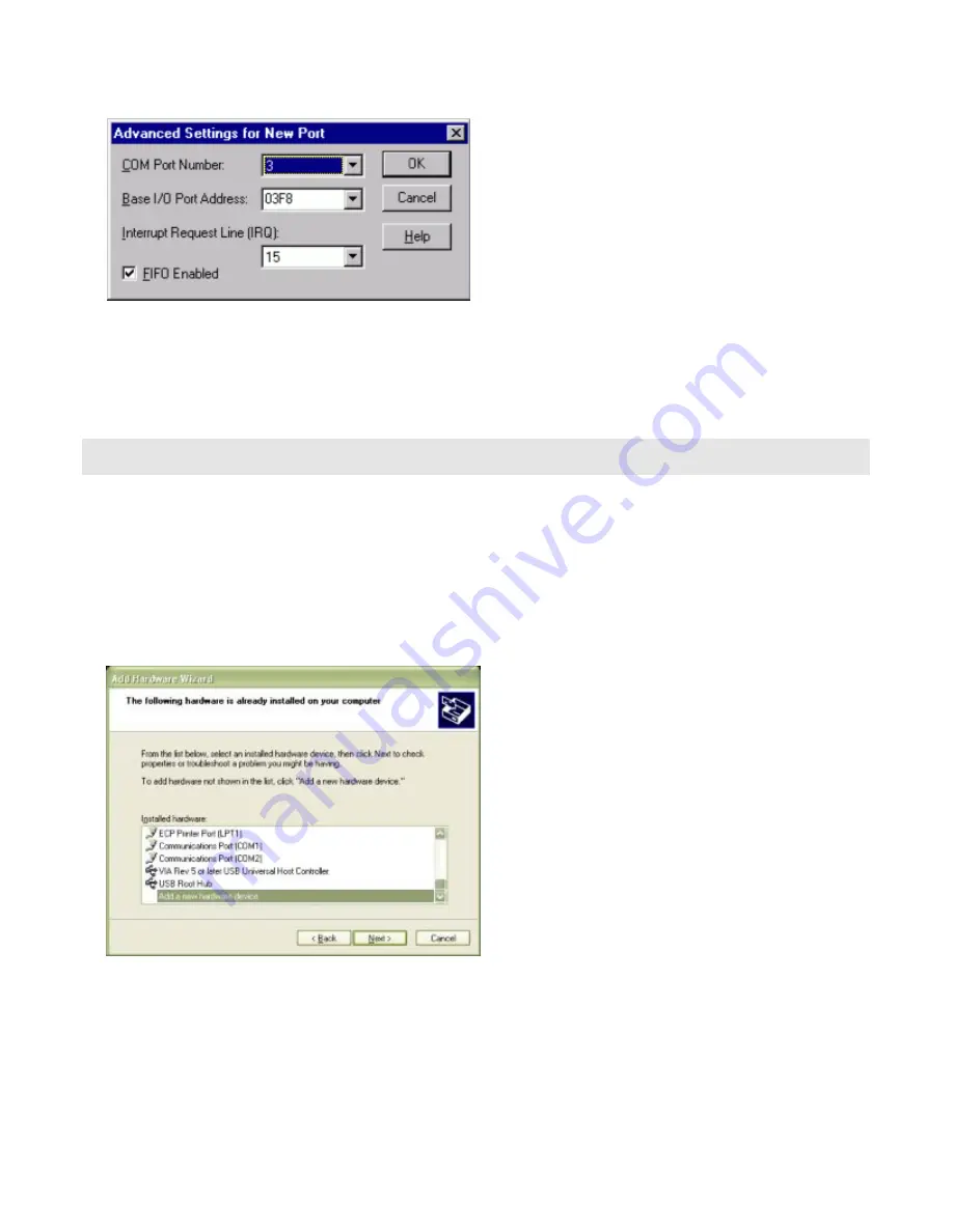
To add a COM port, use START|CONTROL PANEL|PORTS applet and click ADD, then enter the correct UART 
address and Interrupt number.  

When the “Add New Port” dialog is configured click OK, but answer “Don’t Restart Now” when prompted, until 
you’ve added any other ports as well. Then restart the system normally, or by selecting “Restart Now.” 
 

Windows XP


To install the COM ports in Windows XP you will be manually installing “standard” communications ports, then 
changing the settings for resources used by the ports to match the hardware. 

Run the “Add Hardware” applet from the Control Panel. 

Click “Next” at the “Welcome to the Add New Hardware Wizard” dialog. 

You’ll briefly see a “...searching...” message, then 

Select “Yes, I have already connected the hardware” and Click “Next” 


Select “Add a new hardware device” from the bottom of the list presented and Click “Next.” 

Select “Install the hardware that I manually select from a list” and Click “Next.” 

Select “Ports (COM & LPT) and Click “Next” 

Select “(Standard Port Types)” and “Communications Port” (the defaults), Click “Next.” 

Click “Next.” 

Manual 104-COM-8S 

9

Summary of Contents for 104-COM-8S

Page 1: ...ess underutilized and idle equipment along with credit for buybacks and trade ins Custom engineering so your equipment works exactly as you specify Critical and expedited services Leasing Rentals Demo...

Page 2: ...an Diego CA 92121 y 858 550 9559 y Fax 858 550 7322 contactus accesio com y www accesio com EIGHT OR FOUR PORT RS 422 485 PC 104 SERIAL COMMUNICATION BOARD MODELS 104 COM 8S AND 104 COM 4S USER MANUAL...

Page 3: ...ers IBM PC PC XT and PC AT are registered trademarks of the International Business Machines Corporation Printed in USA Copyright 2003 2005 by ACCES I O Products Inc 10623 Roselle Street San Diego CA 9...

Page 4: ...y warranty Warranty commences with equipment shipment Following Years Throughout your equipment s lifetime ACCES stands ready to provide on site or in plant service at reasonable rates similar to thos...

Page 5: ...ESS ASSIGNMENTS FOR COMPUTERS 15 Table 4 2 ADDRESS JUMPERS 16 Chapter 5 PROGRAMMING 17 Table 5 1 Control Block Register Map 17 Table 5 2 EEPROM Address Map 17 Table 5 3 BAUD RATE DIVISOR VALUES 19 Cha...

Page 6: ...It can drive up to 60 mA on balanced lines and receive inputs as low as 200 mV differential signal superimposed on common mode noise of 12 V or 7 V In case of communication conflict the driver receiv...

Page 7: ...en enabled when the transmitter driver is disabled The board automatically adjusts it s timing to the baud rate of the data NOTE Thanks to this automatic control feature the board is ideal for use in...

Page 8: ...M drive is drive D Please substitute the appropriate drive letter for your system as necessary DOS 1 Place the CD into your CD ROM drive 2 Type B to change the active drive to the CD ROM drive 3 Type...

Page 9: ...ctors together 5 Install I O cables onto the board s I O connectors and proceed to secure the stack together or repeat steps 3 5 until all boards are installed using the selected mounting hardware 6 C...

Page 10: ...cations ports then changing the settings for resources used by the ports to match the hardware Run the Add Hardware applet from the Control Panel Click Next at the Welcome to the Add New Hardware Wiza...

Page 11: ...Click the Set Configuration Manually button Select Basic Configuration 8 from the Settings Based on drop down list Select I O Range in the Resource Settings box and Click the Change Settings button En...

Page 12: ...K Close the Set Configuration Manually dialog and Click Finish Click Do Not Reboot if you wish to install more ports Repeat all of the above steps entering the same IRQ but using the configured Base a...

Page 13: ...m the EEPROM into the appropriate registers Channels A B C and D have individual interrupts and channels E F G and H share a fifth interrupt It is necessary to load interrupt values for all of the cha...

Page 14: ...ORD 5 DosDevices REG_SZ COM6 InterruptStatus REG_DWORD 0x500 PortIndex REG_DWORD 4 Serial6 subkey PortAddress REG_DWORD 0x120 Interrupt REG_DWORD 5 DosDevices REG_SZ COM7 InterruptStatus REG_DWORD 0x5...

Page 15: ...TLD RLD 422 COM B TLD RLD 422 TLD RLD 422 T LD RLD 422 TLD RLD 422 COM D TLD RLD 422 COM F TLD RLD 422 COM H COM C COM E COM G H485 G485 F485 E485 D485 C485 B485 A485 CLK x8 P2 Pin 1 Figure 3 1 OPTION...

Page 16: ...3 060 06F 070 07F 080 09F 0A0 0BF 0C0 0DF 0F0 0F1 0F8 0FF 170 177 1F0 1F8 200 207 238 23B 23C 23F 278 27F 2B0 2BF 2C0 2CF 2D0 2DF 2E0 2E7 2E8 2EF 2F8 2FF 300 30F 310 31F 320 32F 370 377 378 37F 380 38...

Page 17: ...A7 A6 A5 A4 Hexadecimal Value 200 100 80 40 20 10 In order to read the address jumper setup assign a binary 1 to jumpers that are not installed and a binary 0 to jumpers installed For example as illu...

Page 18: ...in the EEPROM as shown on the EEPROM address map below Table 5 2 EEPROM Address Map EEPROM Address EEPROM Data Meaning 1 Address for Channel A 2 Address for Channel B 3 Address for Channel C 4 Addres...

Page 19: ...iate registers with a single write to base address 3 SAMPLE PROGRAMS There are two sample programs installed with the CD that is shipped with the board These are Sample 1 This program is provided in C...

Page 20: ...3 0x80 You then load the divisor into Base Address 0 low byte and Base Address 1 high byte The following equation defines the relationship between baud rate and divisor desired baud rate crystal frequ...

Page 21: ...tion is accomplished by constantly reading the Line Status Register at Base Address 5 Bit 0 of this register is set high whenever data are ready to be read from the chip A simple polling loop must con...

Page 22: ...lag If it is high the transmitter has sent the data The process of checking the bit until it goes high followed by a write is repeated until no data remains The following C code fragment demonstrates...

Page 23: ...und 7 Ground Ground 32 Ch F Tx and Rx Ch F Tx 8 Ch B Tx and Rx Ch B Tx 33 Ch F Tx and Rx Ch F Tx 9 Ch B Tx and Rx Ch B Tx 34 Ground Ground 10 Ground Ground 35 Ch F Rx 11 Ch B Rx 36 Ch F Rx 12 Ch B Rx...

Page 24: ...receivers allowed on line Address ISA BUS address is set by jumpers on the board Channel addresses are always loaded from non volatile memory Interrupts Individual IRQs for each channel are stored on...

Page 25: ...wires A balanced line driver will produce a differential voltage from 2 to 6 volts across its output terminals A balanced line driver can also have an input enable signal that connects the driver to...

Page 26: ...the RS422 and RS 485 mode the receiver end of the cable should be terminated with a resistance equal to the characteristic impedance of the cable The exception is when the line is driven by an RS422 d...

Page 27: ...e common mode voltage limit is extended and is 12V to 7V Since any driver can be disconnected or tristated from the line it must withstand this common mode voltage range while in the tristate conditio...

Page 28: ...give us some feedback please email us at manuals accesio com Please detail any errors you find and include your mailing address so that we can send you any manual updates 10623 Roselle Street San Dieg...

Page 29: ...uipment Have surplus equipment taking up shelf space We ll give it a new home Learn more Visit us at artisantg com for more info on price quotes drivers technical specifications manuals and documentat...

Reviews: