background image

Customer Service: (888) 922-2336 

7:00 am to 12:00 am CST (daily) 

Live Chat at: www.academy.com 

Email: 

[email protected]

Made in China

Please keep this instruction manual for future reference

Assembly Instructions

& User

’s Manual

44

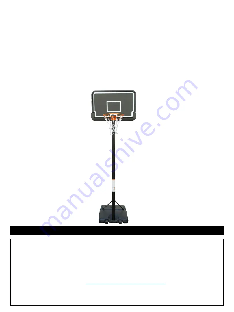
Portable System

170104

Summary of Contents for 170104

Page 1: ...6 7 00 am to 12 00 am CST daily Live Chat at www academy com Email customerservice academy com Made in China Please keep this instruction manual for future reference Assembly Instructions User s Manua...

Page 2: ...nt list and hardware contents If any part is missing or damaged do not attempt to assemble the unit Contact customer service for replacement parts Warnings 2 3 Tools and Parts 4 5 Hardware 6 Assembly...

Page 3: ...other sharp objects which could lead to the base leaking and losing stability Keep organic materials away from the base 4 People should not push or drag the base on the ground to avoid any damage 5 T...

Page 4: ...n and to reduce the risk of accident or injury A high probability of serious injury exists if this system is not installed If using a ladder during assembly use extreme caution Check base daily for le...

Page 5: ...e beginning assembly read the instructions and identify parts using the hardware identifier and parts list in this document Proper and complete assembly use and supervision are essential for proper op...

Page 6: ...ole Axle 1pc 2 Lower Left and Right Brace 2pcs 3 Back Brace 1pc 4 Top Pole Dia 70mm 109cm 1pc 5 Middle Pole Dia 75mm 109cm 1pc 6 Lower pole Dia 80mm 109cm 1pc 7 Rim 1pc 8 Backboard 1pc 9 Net 1pc 10 Wh...

Page 7: ...PCS B Bolts Washer and Nuts M10 85mm 2 PCS C Bolts Flat Washer Spring Washer and Nuts M8 40mm 4 PCS D Bolts Washer and Nuts M10 16mm 2 PCS E Adjustable Knobs M10 25mm 2 PCS F Bolts Washer and Nuts M8...

Page 8: ...e attached on the base Part 11 with bolts and nuts part A Note the curved end of pole is what attaches to the support frame Tools required Allen wrench and wrench Step 2 First slide the Axle part 1B t...

Page 9: ...3 Insert wheel axles part 1A through wheels part 10 and snap in wheels to designated location of base part 11 Step 4 Attach the Lower Left and Right Brace part 2 to the Lower pole part 6 with bolt an...

Page 10: ...ructions Step 5 Attach Rim part 7 to front of the Backboard part 8 inserting 4 bolts part C through rim part 7 backboard part 8 and back brace part 3 Hand tighten bolts to complete backboard assembly...

Page 11: ...t B Note Ensure adjustment holes in top pole Part 4 are facing away from backboard Open the Y brace until the holes are aligned to the holes in the backboard Secure with two bolts Part D Now secure ba...

Page 12: ...on the Rim Part 7 Step 8 Page 11 of 17 Insert top pole part 4 into middle pole part 5 Slide to align top pole and middle pole holes Insert knobs part E to align and tighten Stand upright and insert to...

Page 13: ...Completed View Page 12 of 17...

Page 14: ...ctions for Height Adjustment Page 13 of 17 Unscrew the adjustable knobs then move the tube up or down to adjust the height Make sure the two holes on the tubes are aligned then tighten the adjustable...

Page 15: ...s and bolts If any are loose tighten them 2 Check all parts for excessive wear and tear If necessary replace any parts that have been worn or damaged through usage Contact our Customer Service Departm...

Page 16: ...aused by the use of other than genuine parts are not covered by this warranty This warranty shall be effective from the date of purchase as shown in the purchaser receipt This warranty is valid for th...

Page 17: ...tem will tip quickly causing serious personal injury When adjusting height or moving system keep hands and fingers away from moving parts Do not allow children to move or adjust system During play do...

Page 18: ...outh guard when playing to avoid dental injuries WARNING HEIGHT ADJUSTMENT Rest unit on support table Remove adjustment knobs A and carriage bolts B to extend or retract backboard and rim WARNING Back...

Reviews: