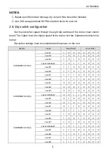
AC Pro AUD24AH2/A1-D Installation Instructions Manual Download Page 13

Air Handlers 

NOTE: 

Please refer to above table for fan speed selection, and ‘-’ is not allowed to be 

used. 

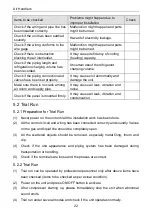
3 Preparative for Installation 

3.1 Pre-Installation Instruction 

3.1.1 Checking Product Received 

After receiving the product, please check if there is any damage caused by 

transportation. Shipping damage is the responsibility of the carrier. Verify the model 
number, specifications and accessories are correct prior to installation. The distributor 
or manufacturer  will not accept claims from dealers for transportation damage or 
installation of incorrectly shipped units.   

3.1.2 Before Installation 

Carefully read all instructions for the installation prior to installing product. Make 

sure each step or procedure is understood and any special considerations are taken 
into account before starting installation. Assemble all tools, hardware and supplies 

Model 

AUD48AH2/A1-D(U)

Level 

Static pressure(Inches W.C.) 

0.1  0.15 

0.2 

0.3 

0.4 

0.5 

0.6 

0.7 

0.8 

0.9 

1.0 

Speed 1(CFM)  1640  1500  1450  1350 

Speed 2(CFM)  1680  1560  1500  1380  1300 

Speed 3(CFM)  1810  1690  1620  1550  1380 

Speed 4(CFM)  1930  1830  1770  1710  1580  1430  1280 

Speed 5(CFM)  2200  2110  2040  1980  1860  1720  1620  1490  1380 

Speed 6(CFM)  2240  2190  2145  2100  2010  1870  1750  1615  1500  1380 

Speed 7(CFM)  2280  2240  2200  2180  2130  2080  2000  1880  1750  1600  1420 
Speed 8(CFM)  2300  2260  2220  2190  2140  2090  2040  1980  1930  1800  1700  1550 

Model 

A

UD60AH2/A-D(U) 

Level 

Static pressure(Inches W.C.) 

0.1  0.15 

0.2 

0.3 

0.4 

0.5 

0.6 

0.7 

0.8 

0.9 

1.0 

Speed 1(CFM)  1660  1540  1470  1400 

Speed 2(CFM)  1850  1720  1650  1600  1400 

Speed 3(CFM)  1920  1800  1730  1650  1480  1315 

Speed 4(CFM)  2110  2000  1950  1860  1760  1640  1490  1325 

Speed 5(CFM)  2250  2200  2190  2140  2040  1930  1800  1670  1520  1370 

Speed 6(CFM)  2260  2220  2200  2170  2090  2010  1910  1760  1650  1550  1430  1380 
Speed 7(CFM)  2300  2260  2230  2200  2150  2115  2050  1990  1920  1840  1750  1660 
Speed 8(CFM)  2320  2280  2250  2230  2190  2140  2080  2040  2000  1950  1920  1890 

Summary of Contents for AUD24AH2/A1-D

Page 1: ...Installation Instructions Original Instructions Air Conditioners Air Handlers Models AUD24AH2 A1 D U AUD36AH2 A1 D U AUD48AH2 A1 D U AUD60AH2 A1 D U...

Page 2: ...improper disassembly and inspection which may impact the normal operation of unit please do not disassemble the unit by yourself You can contact with the special maintenance center of our company if...

Page 3: ...defects are due to improper operation during transportation of product 5 Operate repair maintain the unit without abiding by instruction manual or related regulations 6 After verification the problem...

Page 4: ......

Page 5: ...parative for Installation 7 3 1 Pre Installation Instruction 7 3 2 Important Safety Instructions 8 4 Installation 10 4 1 Unit Inspection 10 4 2 Location 10 4 3 Piping Work 11 4 4 Condensate Removal 13...

Page 6: ...r household wastes throughout the EU To prevent possible harm to the environment or human health from uncontrolled waste disposal recycle it responsibly to promote the sustainable reuse of material re...

Page 7: ...with the kits or accessories when installing Follow all safety codes Wear safety glasses protective clothing and work gloves Use quenching cloth for brazing operations Have fire extinguisher available...

Page 8: ...ning label 2 Product Introduction 2 1 Product Description 2 2 Optional Accessories Indoor unit accessories No Name Appearance Q ty Usage 1 3 8 CPC 1 Copper Pipe Connector Liquid Line 2 3 4 CPC 1 Coppe...

Page 9: ...sical Dimension Unit inch Model Dimension W D H A B AUD24AH2 A1 D U AUD36AH2 A1 D U 21 1 4 21 1 4 48 1 4 11 5 8 20 AUD48AH2 A1 D U AUD60AH2 A1 D U 24 3 4 21 1 4 57 11 5 8 20 Clearance Side and back 0...

Page 10: ...D U 2 0 5 8 10 AUD36AH2 A1 D U 3 0 5 8 10 AUD48AH2 A1 D U 4 0 10 15 20 AUD60AH2 A1 D U 5 0 10 15 20 Model Motor 230V 60Hz HP FLA AUD24AH2 A1 D U AUD36AH2 A1 D U 1 2 2 1 AUD48AH2 A1 D U AUD60AH2 A1 D...

Page 11: ...AUD24AH2 A1 D U Level 1 1 0 0 0 0 0 0 0 Level 2 1 0 0 1 0 0 0 0 Level 3 1 0 1 0 0 0 0 0 Level 4 Default 1 0 1 1 0 0 0 0 Level 5 1 1 0 0 0 0 0 0 Level 6 1 1 0 1 0 0 0 0 Level 7 1 1 1 0 0 0 0 0 Level 8...

Page 12: ...60 Speed 5 CFM 1580 1490 1440 1390 1290 1180 1090 970 830 Speed 6 CFM 1720 1640 1600 1550 1450 1360 1250 1130 960 Speed 7 CFM 1800 1730 1680 1630 1550 1460 1370 1270 1150 970 830 Speed 8 CFM 1850 1820...

Page 13: ...l AUD48AH2 A1 D U Level Static pressure Inches W C 0 0 1 0 15 0 2 0 3 0 4 0 5 0 6 0 7 0 8 0 9 1 0 Speed 1 CFM 1640 1500 1450 1350 Speed 2 CFM 1680 1560 1500 1380 1300 Speed 3 CFM 1810 1690 1620 1550 1...

Page 14: ...labels are used throughout this manual to indicate immediate or potential hazards It is the owner s responsibility to read and comply with all safety information and instructions accompanying these sy...

Page 15: ...e reconfigured to operate with any other power supply The unit must have an uninterrupted unbroken electric grounding to minimize the possibility of personal injury if an electric fault occurs The ele...

Page 16: ...ly to the carrier Do not install such an equipment damaged by freight which determines the integrity and safety of the unit Please check the equipment model number to ensure the unit is appropriately...

Page 17: ...stalled as Fig A the air handler should be concealed in a specific room or space and make sure the air handler is not accessible to the general public Based upon the actual conditions if air handler i...

Page 18: ...Air Handlers 12 4 3 2 Piping Preparation 4 3 2 1 Solder Connection All cut ends are to be round burr free and cleaned Failure to follow this practice increases the chances for refrigerant leakage...

Page 19: ...revent rain water from pouring in and cause property loss or personal injury 3 Condensate drain pipe should be connected into special drain system for air conditioner 4 The drain pan has primary and s...

Page 20: ...urn air filter This filtering may be performed at the air handler or externally such as a return air filter grille 4 6 Electric Heater The air handlers listed in this manual do not have factory instal...

Page 21: ...losed area such as a garage or utility room with any carbon monoxide producing appliance ensure the area is properly ventilated 1 Refer to the Table for appropriate heater kit 2 Check any physical dam...

Page 22: ...tions and the instructions in this manual Never extend the power cords The electric circuit must be equipped with a circuit breaker and air switch both with sufficient capacity The unit s operating po...

Page 23: ...er cables that are delivered along with the air conditioner Do not change the power cables arbitrarily Do not change the length and terminals of the power cables If you want to change the power cables...

Page 24: ...lease adjust the specifications according to national standards Adopt 5pc of AWG18 power cords to be the communication cords between indoor unit and thermostat The maximum length is 98ft Please select...

Page 25: ...Unit inch 3 How to connect the thermostat wires and power cords Lead the thermostat wires and power cords through the insulation tube Then fix the wires with wire clamps as shown in the following figu...

Page 26: ...wire should be connected Wires of indoor unit Only for air handler without electric heater NOTE Y means Compressor control signal for the outdoor unit B which is energized under the heating mode means...

Page 27: ...unit through connecting the ground wire The units should comply with applicable local and national rules and regulations on power consumption When connecting the power cords make sure the phase sequen...

Page 28: ...cause air leak vibration and noise Check if the panel is mounted firmly It may cause air leak vibration and condensation 5 2 Trial Run 5 2 1 Preparative for Trial Run 1 Never power on the unit until...

Page 29: ...blocked Remove obstacles Inappropriate temperature setting Adjust setting at thermostat Doors or windows are opened Close the door or windows Direct sunshine Draw curtain or louver Too much heat sourc...

Page 30: ...Indoor fan can be set as ON or AUTO mode Under ON mode indoor fan will keep running after switch off the unit There are LED indicators on the main board of the indoor unit which are used to display t...

Page 31: ...f the unit 2 Clean filter screen of indoor units 3 Clean the dust of sundries on the indoor units 4 In the event of rusting use the anti rust paint to stop spreading of rust 7 4 Parts Replacement Purc...

Page 32: ...0DWHULDO 6XSSO QF GED 3UR Add 11700 Industry Ave Fontana CA 92337 USA Tel 1 951 360 0630 E mail www acpro com...

Page 33: ...red CommunicationWiring guidelines Dip Switch setting for Capacity Fill in Project Name Model Serial Continue on back X Series Pre Commissioning Checklist Checklist to prepare for commissioning use pr...

Page 34: ...lb Fill in Amp Current Draw Fill in ForTech Support Assistance please have this checklist completed first then call 855 972 2776 reversing valve is energized in heat Start up guidelines Once all of th...

Reviews: