background image

2. Start Up Guide

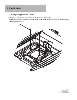
2-4. Adjusting the Grab Cradle

1. The grab cradle will be preset from the factory for a 5.00-5 tire.   
    Measure the distance between the top of the grab blade points. For a 5.00-5 tire this should 
   measure around 5-1/8”. 

Summary of Contents for AC Tracktech T-MINI with Grab Cradle

Page 1: ...Instruction Manual MODEL AC Tracktech T MINI with Grab Cradle World s First Portable Remote Control Aircraft Tugs 95488 Rev B ...

Page 2: ...ion 2 2 Operating the Tug 2 3 Loading onto Tug 2 4 Adjusting Grab Cradle 2 5 Adjusting the Track Tension 2 6 Unloading the Tug 2 7 Charging the Tug 2 8 Charging the Transmitter 2 9 Replacing Transmitter Batteries 2 10 Spare Parts 2 11 Track Tools 3 Warranty ...

Page 3: ...1 Components Tug Tug Charger Radio Transmitter Battery Tray Radio Charger Owners Manual Spare Parts Bag ...

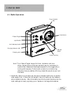
Page 4: ...o replace or recharge the batteries Note The 3 Speed Toggle ranges from fast moderate and slow When operating the tug at slow speeds it may be neccessary to switch to the moderate or fast speed position on the toggle when turning at 90 degrees Factors such as terrain and incline may affect the maneuverability of the tug Adjust the speed at your own discretion Control Stick Latch Release Switch Pow...

Page 5: ...ote it is recommended that the power switch be turned OFF Note If the remote is not used for more than a couple minutes it will start beeping as a indicator that it is still in the ON position This is not an indicator of a low battery 2 To drive the tug move the control stick in the desired direction Forward Right Reverse Left Reverse Right Forward Left ON ...

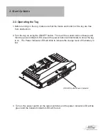
Page 6: ...There will be a short series of beeps and then the power indicator LED around the power button will illuminate to show the tug is on The Power Indicator LED will blink to indicate the charge level of the battery is low 3 Turn on the power switch on the radio controller and the power indicator LED will be green and the transmit indicator LED will be red ON OFF Button Power Indicator ...

Page 7: ... plastic surfaces Also inspect for damaged or missing rotoclips as a result of driving over small rocks Damaged threads should be replaced before operating the tug Note The circuit breaker reset button will trip if the tug is overloaded The circuit breaker button is white and is located on the PC board towards the center To reset the circuit breaker open the top cover to push the reset button down...

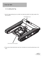
Page 8: ...the cradle and position the wheel cradle in the down position 2 3 Loading onto Tug 2 Start Up Guide Wheel cradle in down position Cradle Release Lever 2 Place wheel chocks behind the main tires of the plane to ensure the plane does not roll back ...

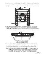
Page 9: ...ug Under The Tire 4 When the tire contacts the back roller then continue slowly while the tire pushes the roller and the grab blades are lifted up on both sides of the tire Watch the grab blades on both sides of the tire to make sure they are not too tight on the tire that they are not allowed to pivot up freely Continue loaing until the cradle is locked in the up position Warning If the grab blad...

Page 10: ...ide 2 4 Adjusting the Grab Cradle 1 The grab cradle will be preset from the factory for a 5 00 5 tire Measure the distance between the top of the grab blade points For a 5 00 5 tire this should measure around 5 1 8 ...

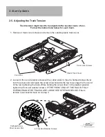
Page 11: ...2 Take note of the location of the 4 adjuster screws on the adjuster blocks Each adjuster block has two sets of 4 holes with 2 screws in each adjuster Adjuster Screws Adjuster Blocks ...

Page 12: ...djuster block can change from their previous locations and the front set can be different from the rear set Remove Adjuster Screws from Adjuster Blocks Front Set Rear Set 4 Re install adjuster screws into the adjuster blocks 4 total screws Measure the distance between the grab blade points to verify their new spacing is larger or smaller than your initial measurement in step 1 5 Try loading the ai...

Page 13: ...nsert a flathead screw driver into the access slot and push the screw driver towards the tug to leverage the front end of the rail tightening the track While holding the screw driver in the desired position tighten the front end retainer screws IF THE FRONT END OF THE RAIL IS FULLY EXTENDED AND THE TRACKS ARE LOOSE SEE STEPS 2B BELOW If track tension is successful move on to step 3 Track Cover Scr...

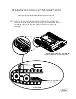
Page 14: ... with the edge of the tug main plate once the front end is fully extended 2B Adjusting Track Tension on a Fully Extended Front End The tug spare parts kit provided with the tug will be required Front View Indicator line aligns with tug main plate The image depicts a different model T Mini but the track procedure will work for the T Mini Grab Cradle model ...

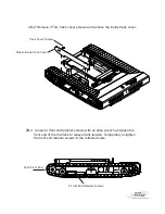
Page 15: ...end of the the track to relieve track tension Temporarily re tighten the front end retainer screws in the retracted state 2B 2 Remove 3 Torx track cover screws and remove the inside track cover Track Cover Screws Plastic Inside Track Cover Push Front End 4 Front End Retainer Screws ...

Page 16: ...k pins with the Rotorclips on the opposite end intact and 2 track links Tip Tap the end of the track pin using a hammer to drive the pin through the Rotoclip The Rotoclip will not be reusable after removal Tap Track Pin Here Rotoclip and Pin Intact Discard Rotoclips Track Link ...

Page 17: ... Rotoclip into Retainer Clip Tool Teeth pointing towards clip tool Track Pin Track Pin and Rotoclip New Rotoclip Retainer Clip Tool Apply pressure on end of pin when inserting the clip on the other end 2B 7 Inspect the track pin and Rototclips The Rotoclips should rotate freely inside the pin groove Reinstall the Inside Plastic Track Cover Section 2B is complete proceed to step 2 for adjusting tra...

Page 18: ... There should be about a 1 2 of play at the center of the track 1 2 Up and Down Play at Center of Track 4 Reinstall the plastic track covers Install Plastic Track Cover 5 Repeat steps for the other track ...

Page 19: ...puts pressure on the back gate of the cradle The back gate is the gate that is closest to the latch mechanism 4 While holding a slight pressure on the back gate release the latch by holding the latch release button on the radio 5 While still holding the latch release button move the tug away from the tire 6 The front gate should go down and the grab blades should pivot down also allowing the airpl...

Page 20: ... the charger is connected properly The tug will be fully charged once the charge indicator light turns green It is recommended to leave the tug charging when not in use 3 Once it is fully charged unplug the charger and turn the tug on Then turn the tug off for a few seconds and back on again This will resets the tug It is now ready to be used Charging Jack Charging Indicator Light ...

Page 21: ...2 Plug the connector from the charger into the charging jack on the transmitter The charging indicator LED located on the side of the transmitter will illuminate green indicating the charger is charging Once the transmitter is fully charged the charging indicator LED will turn off 3 The charging rate of the charger is 150mAh When using the 1200mAh batteries that are supplied the radio requires an ...

Page 22: ...ews from back of transmitter case 2 Replace old battery pack with new battery pack Note A battery tray is provided with the tug It can be used with standard AA rechargable batteries Refer to section 2 9 2 Start Up Guide No Battery Access Cover Screws Back Cover ...

Page 23: ...ble AA Lithium Ion batteries Refer to section 2 9 in the owners manual 5A Reconnect the battery to the transmitter circuit board 6A Re install back cover and screws Note A shrink wrapped battery pack can be purchused from AC Air Techology to replace the installed battery tray To use a shrink wrapped battery pack 1 Disconnect the battery tray from the transmitter circuit board 2 Connect the new shr...

Page 24: ...Up Guide 2 10 Spare Parts Rotoclips s d a e r T s k n i L Spare Track Parts Pins Fuses 4A mp Replacement Light Fuse 10 Amp Replacement Circuit Board Fuse Track Install Tools Track Pin Tools Retainer Clip Tool 4 ...

Page 25: ... instruction guide is provided when purchasing new tracks Refer to that instruction guide when installing new tracks Note Track Pin Track Pin Groove Rotoclip Teeth Facing Outward When Rotoclip is properly installed in the track pin groove it should rotate freely inside of the groove Retainer Clip Tool Rotoclip Teeth Pointing Down Track Pin 2 11 Track Tools ...

Page 26: ...the installation of new tracks Insert the Track Pin Tools on the inside and outside adjacent pins to the missing pin hole Note You will need to hold these in place by hand Track Pin Tool Track Pin Tool Missing Pin Hole Adjacent Pin Adjacent Pin ...

Page 27: ...n use modification or misuse of this product thus no liability shall be assumed or ac cepted for any resulting damage or injury By the first act of use set up or assembly the user in using the product accepts all resulting liability Failure to operate this product in a safe and responsible manner can result in damage or injury both to the user as well as to others the product or property This prod...

Reviews: