

Mini FunFly Flight Controller “Naze32” (
なぜ)
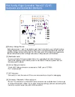
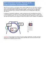
Hardware and Connection (Top)
1
2
3
4
8
Battery Connector
for Voltage Monitor
RC
Input
(CPPM/PWM)
6 ESC/Servo
Headers
Buzzer connector
USB Port
Power LED
M3 mounting hole
30.5mm spacing
[1] ESC / Servo Headers
[2] RC Input / Servo Output (CPPM / PWM) / GPS connector
“Front” direction
Status LEDs
6 motors or 4 motors and up to 2 servos can be connected here. The pins towards
center of the board are signal pins. Following that is 5V, and then Ground/GND pins.
WARNING
Incorrect or reverse connection to these connectors will instantly destroy
the hardware.
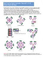
With the connector facing out, the pins are used as follows. Unmarked pin
(left-most top side) is ground, pin marked with dot is 5V, the rest are RC
signal pins for CPPM (channel 1) or channels 1 through 8. Standard male to
male servo cable can be used to connect a CPPM receiver, then individual
connectors going to ‘signal’ pins for any additional PWM channels.
[3] Buzzer
5V Buzzer, connect a header here, + and - are marked and should be followed.
Board is 36x36mm square, with mounting holes for M3 screws, spaced 30.5mm.
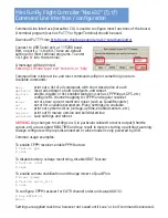
* 1 2 3
4 5 6 7 8
In CPPM input mode, Channels 3 and 4 can be used for
3.3V
GPS connection. (3:TX, 4:RX),
and Channels 5 to 8 can be used for motor outputs.


