


62
x
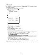
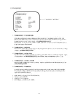
65 + preset: “Status Report” is displayed, if user wants to remove this screen, press
Focus Near button.
x
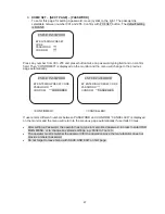
70 + preset: This feature provides picture stabilization image.
This feature is available only by entering the preset number and is not included in OSD main
menu.
x
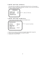
92 + preset: With this feature it is possible to freeze the current picture during tour, auto scan or
pattern operation. When 92 + preset button has been pressed, the image stops but the camera
is still working as per operation such as tour, pattern or auto scan. To return to operating image,
press 92 + preset button again. This feature is available only by enter the preset number and is
not included in OSD main menu.
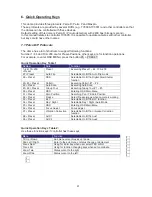
7.2 Maxpro Protocol
If you want to choose Maxpro Protocol, the user must change the dip switch first.
Baud Rate: 9600 (Maxpro default)
Maxpro protocol is almost same as Pelco D/P protocol operating system but some special features
are different way as noted below:
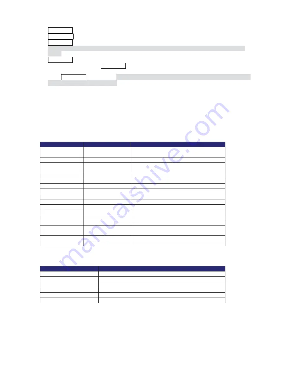
Quick Operation Key Table 1
Number
Note
Function
1~64,100~200
+Preset
Preset
Executing Preset 1 ~ 64, 100~200
67 +Preset
Auto Flip
Selectable On/Off in Auto Flip mode
69 + Preset
DSS
Selectable On/Off in Digital Slow Shutter
function
80~85 + Preset
Pattern
Executing Pattern #1 ~ #6
86 + Preset
Auto Scan
Executing Auto Scan
87~89 + Preset
Group Tour
Executing Group Tour #1 ~ #3
90 + Preset
OSD
Entering OSD Main Menu
91 + Preset
Zero Position
Searching Pan / Tilt Zero Position
92 + Preset
Freeze
Select Freeze image when camera is working
93 + Preset
BLC
Selectable On/Off in BLC function
94 + Preset
Day / Night
Selectable Day / Night / Auto Mode
95 + Preset
OSD
Entering OSD Main Menu
96 + Preset
Focus Adjust
Focus adjust
97 + Preset
Vibration Correction
Selectable On/Off in Vibration Correction
function
98 + Preset
AUX 1
Selectable On/Off in Aux1
99 + Preset
AUX 2
Selectable On/Off in Aux2
Quick Operation Keys Table 2:
Use these function keys if controller has these keys
Menu
Function
Tilt Up / Down
Sub menu cursor moves up / down
Pan Left / Right
Enter to the sub menu or status change or decrement
Focus Near
Using for Enter key when user select YES or NO
Focus Far
Using for function changing keys when set coordinate
Zoom Tele
Status cursor to the right
Zoom Wide
Status cursor to the left


