background image

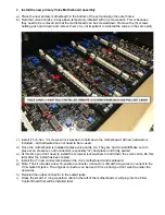
c)  Note: There is no connection to the 4-position header at the bottom of the upper voice motherboard. 


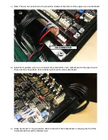
d)  Install the 5-position 

voice sum

 connector from the bottom voice motherboard to the upper board. 

These are the connections at the bottom-right of each voice motherboard. 


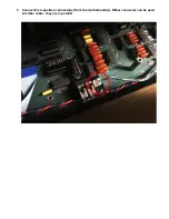
e)  Dress the small 12

” long 4-position cable to the left of the motherboard. It will plug into the Filter 

Control Board that will be installed next. 


Summary of Contents for Oberheim OB-X

Page 1: ...y Expansion 1 Motherboard Tray 1 Filter Control Board 4 10 Position Connectors 1 5 Position Connector 1 4 Position Connector 1 4 Position Power Connector 1 4 Position DF13 style connector pre plugged to voice motherboard Mounting hardware for mounting motherboard tray voice cards and filter control board 8 Voice Kit 8 OB X Voice Card Assemblies 1 OB X Motherboard Assembly Primary 1 OB X Motherboar...

Page 2: ...between the upper voice tray and mainboard The connectors can be discarded as new connectors are included in the kit b Remove the 5 position connector on the right side of the voice motherboard c Remove 3 screws from the bottom of the OB X that are holding the 3 1 standoffs to the left side of the upper voice tray Alternately remove the 3 6 32 nuts from the top side of the unit and leave the stand...

Page 3: ...r to the output jacks b In order to remove the voice motherboard voice cards 2 4 must be removed first To remove the voice cards remove the 6 6 32 screws holding down each card and pull out the cards c After voices 2 4 are removed remove the 15 6 32 screws holding down the voice motherboard d Remove the voice motherboard assembly With the voice motherboards removed you see the bottom of the enclos...

Page 4: ...board is installed replace voice cards 2 4 They are hard to install Make sure to place even pressure on all connectors especially G and press until firmly seated e At this time you don t need to install the screws lock washers to hold down the voice cards Do this later after the install has been tested f Install the 7 new connectors between the voice motherboard and mainboard g Note The kit includ...

Page 5: ...stall 3 6 32 screws and lock washers from the bottom of the unit to attach the standoffs e Do not install the screws on the right side of the tray yet The tray swings open and it should be left as is until the voices are tested verified 2 Install Connectors a Install the 6 new connectors between the upper voice motherboard and the mainboard b If upgrading from a 4 voice OB X there may be a dummy l...

Page 6: ...all the 5 position voice sum connector from the bottom voice motherboard to the upper board These are the connections at the bottom right of each voice motherboard e Dress the small 12 long 4 position cable to the left of the motherboard It will plug into the Filter Control Board that will be installed next ...

Page 7: ...STALLATION FILTER CONTROL BOARD 1 Remove screw from CPU Board Note If the Encore MIDI Kit is installed it should be first removed to access the CPU board 2 Swing open CPU Board and remove IC31 screw shown ...

Page 8: ...3 Install the included male female standoff where shown 4 Install the Filter Control Board into socket IC31 Secure it to the standoff with a 6 32 screws lock washer ...

Page 9: ...5 Connect the 4 position connector s from the motherboard s Either connector can be used w either cable they are in parallel ...

Page 10: ...o longer works 2 When the right BP switch is in the up position the NOISE HALF button will select bandpass mode and noise half no longer works Please note The 4 Voice expansions were shipped with the filter control board included If it installed you can use it to have different filter modes for the top four voices The bottom four voices will not have filter control and you will lose the noise half...

Reviews: