background image


- 22 - 


KLCOB V2 Series


User Manual


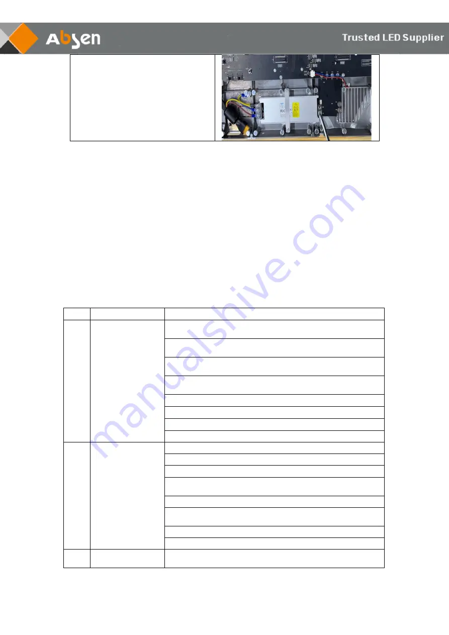
Use  a  PH2  Phillips  screwdriver  to 

remove  the  fixing  power  supply  screw 
to  directly  replace  the  faulty  power 
supply 


5.2.3 Precautions for use 

1. Pay attention to anti-static when touching LED light boards and panels, and do the 

following effective protection: 

a. Wear a grounded electrostatic wrist strap or electrostatic gloves; 
b. The screen is strictly grounded, and the grounding resistance is required to be ≤10 
ohms, and a point inspection is carried out every six months; 

2. When cleaning the surface of the lamp panel, do not use unknown chemical liquids, 

but use a clean dust-free or clean water damp cloth to wipe lightly; 

3. The distribution box is required to have protective facilities such as surge protectors. 

 6. Common faults and troubleshooting 

No. 

Common faults 

Solution 

Some modules are 

black 

1. Check whether the power plug of the corresponding 
module is tightly inserted; 
2. Check whether the power cable of the corresponding 
module is burnt out; 
3. Check whether the switch power supply of the 
corresponding module has no output; 
4. Check whether the flat cable of the corresponding 
module is malfunctioning; 
5. Replace the flat cable of the corresponding module; 

6. Replace the module; 

7. Replace the receiving card; 

8. Send rcfg file; 

The whole screen 

is black 

1. Check whether the screen power is on; 

2. Check whether the DVI cable or HDMI cable is loose; 

3. Check whether the main data cable is well inserted; 

4. Check whether the controller is powered on and whether 
the running indicator is flashing; 
5. Replace the controller; 

6, Connecting the computer to an LCD display, check 
whether there is output on video card; 
7. Update the video card driver; 

8. Replace the computer; 

Screen show scra

mbled image 

1. Check whether the power plug of the receiving card is 
well inserted; 

Summary of Contents for KLCOB V2 Series

Page 1: ...KLCOB V2 Series User Manual Shenzhen Absen Optoelectronic Co Ltd...

Page 2: ...binet Introduction 9 2 2 Product Component Drawing 9 3 Product Installation 11 3 1 Steel structure installation 12 3 2 Wall mounting installation 13 3 3 Hanging installation 14 4 Product Cabling 15 4...

Page 3: ...er suitable lightning protection If the equipment is not in use for a long time please unplug the power cord When performing any installation or maintenance work e g removing the fuses etc make sure t...

Page 4: ...ing repairing or moving the product ensure the working area is free of obstacles and ensure the working platform is securely and stably fixed In the absence of proper eye protection please do not look...

Page 5: ...Rules These limits are designed to provide reasonable protection against harmful interference when the equipment is operated in a commercial environment This equipment generates uses and can radiate r...

Page 6: ...credible images Cool Stay cool enjoy more Thanks to the flip chip LED technology and Absen s HBB technology the KLCOB can always stay cool diving into the fantastic visual world without breaking a swe...

Page 7: ...ing 20bit internal processing 19bit internal processing 19bit internal processing Refresh Rate Hz 3840 Contrast Ratio 15000 1 Color Temperature K 6500 Viewing Angle H V 160 160 Driving Type 1 48 1 54...

Page 8: ...8 KLCOB V2 Series User Manual 1 3 Cabinet dimension figure mm 1 4 Module dimension figure mm The module size is 150 x168 75mm each panel has 8 modules...

Page 9: ...2 2 1 Mounting frame used for wall mounting including single and double frames 2 2 2 Hanging bar used for hanging installation Including double and triple frame Handle Test button Powerout Position P...

Page 10: ...el structure 2 2 4 Data Jumper for vertical connections in between cabinets Standard Version 300mm long 2 2 5 Power cable Specification 3 2 5mm 10m Specification 3 2 5mm 0 9m Used for adjacent column...

Page 11: ...allation In order to ensure the visual effect the cabinets and modules need to be installed in the exact position The rules are as follows cabinet number XX Screen number XX Row number XX cabinet numb...

Page 12: ...number 3 1 Steel structure installation Installation is from the bottom to the upper layer first lock the connection screw between the panel and then use the connection piece and the M6x60mm screw to...

Page 13: ...self tapping screws or M6 expansion screws to fix the wall mounting frame on a flat wall Step 2 Install the screw on the mounting holes and install 4 screws on each panel Step 3 Install the panel fram...

Page 14: ...es is needed Installation steps a Fixed the hanging bar on the structure b Align the screw holes of the panel with hanging bar and fixed the panel c Install other panels and tighten the screws in four...

Page 15: ...lying power and signal source to the screen please check power and data cables connections carefully and make sure they are wired correctly Use a multimeter to test the L N and PE lines in AC power in...

Page 16: ...ol card receives signals from the controller to control each LED pixel The control card is composed of multiple components including MCU memory interface chips etc and can process data store correctio...

Page 17: ...ulate and select the appropriate model of distribution box or socket according to the maximum power consumption Please consult your electrician or distribution cabinet manufacturer for specific select...

Page 18: ...T5 network cable and the network cable interface of the cabinet can be used for input and output For the S type of up down connection please calculate the resolution according to the pixels of each ca...

Page 19: ...rocesses the data to controlling each LED pixel The HUB card plays the role of signal distribution Note The range of loaded pixels of each net port cannot exceed 655360 points as shown in the followin...

Page 20: ...e instructions 5 2 1 module maintenance KLCOB V2 series modules can be quickly removed using passive front maintenance Open the handle of the front maintenance tool place the front maintenance tool on...

Page 21: ...se a screwdriver to remove the screw fixing the HUB board for replacement HUB board maintenance Picture After removing the module with the maintenance tool remove the current equalizing wire on the HU...

Page 22: ...lution 1 Some modules are black 1 Check whether the power plug of the corresponding module is tightly inserted 2 Check whether the power cable of the corresponding module is burnt out 3 Check whether...

Page 23: ...hecontroller is powered on and whether the running indicator is flashing 4 Replace the module 5 Replace the receiving card 5 All panels display the same content 1 Set the screen connection on software...

Page 24: ...24 KLCOB V2 Series User Manual All rights reserved by Shenzhen Absen Optoelectronic Co Ltd Shenzhen Absen Optoelectronic Co Ltd reserves the rights to modify contents without any further notice...

Reviews: