background image

Above

Air


MissionCritical

 A/C’s

AboveAir


Technologies

 (MC22-L12)

16

Guide Specifications

  Guide Specifications -


MC

-

2x2

 Mission

Critical

 (1-3 Tons)

2.5 Accessories

  2.5.1  Plenum Discharge Box


(UF - Up-Flow Units)

A (2-way, 3-way or ducted) plenum 

discharge box shall be provided for field 

installation to the top of the up-flow unit.  

The plenum box shall be 18.5 inches 

high, insulated and powder-coat painted 

to match the color of the unit.


2.5.2  Floor Stand

A ____ inch high floor stand shall be 

factory provided for field installation.  The 

floor stand shall have adjustable legs 

with vibration isolation.

  2.5.2.1  Turning Vanes

Turning vanes shall be factory provided 

with the floor stand to direct the dis

-

charge air either to the front or rear of 

the unit.

  2.5.3  Condensate Pump


  (Factory Installed - UpFlow)

A condensate pump shall be factory 

provided and installed within the indoor 

evaporator section

 (Up-Flow Air Pattern 

Configurations)

.  The condensate pump 

shall be provided with dual internal float 

switches: one for pump operation initia

-

tion and the other for pump reservoir 

overflow safety.

(

Note:

  Down-Flow unit Condensate Pump 

Option requires field installation of the pump 

outside of the A/C unit.  A condensate pump 

fused power supply terminal connection 

shall be factory provided within the A/C unit 
evaporator.)


2.5.4    Hot Gas Bypass Systems


2.5.4.1  Hot Gas Bypass To


    Evaporator Inlet

Each refrigerant circuit shall be pro

-

vided with a factory installed hot gas 

(discharge) bypass valve.  The hot gas 

bypass valve shall be designed to supply 

hot gas to evaporator inlet as required to 

provide coil freeze-protection and capac

-

ity modulation under low load conditions.


2.5.4.2  Hot Gas Bypass To 


    Suction Line with


    Quench Valve


(VCH/XPU-CCU/CWU-CGU 


    Remote Condensing Units 

      3

rd

 Line Not Required!)


Each refrigerant circuit of the Split DX 

system shall be provided with a fac

-

tory installed hot gas bypass system to 

include:  hot gas (discharge) bypass and 

desuperheating quench.  The hot gas 

bypass system shall be designed to sup

-

ply hot gas and liquid refrigerant to the 

suction line as required to provide coil 

freeze-protection and capacity modula

-

tion under low load conditions.  All hot 

gas bypass components shall be factory 

installed and shall not require additional 

field refrigerant lines on split DX sys

-

tems.


2.5.5  Suction-Line Accumulator

Each refrigerant circuit shall be provided 

with a factory installed Suction-Line Ac

-

cumulator to prevent liquid slugging of 

the compressor and excessive refriger

-

ant dilution of the compressor oil during 

low load conditions. The accumulator 

shall return refrigerant and oil to the 

compressor at a sufficient rate to main

-

tain both system operating efficiency and 

proper oil level.  The accumulators shall 

be wrapped with a 1/2” closed-cell neo

-

prene insulation to prevent sweating.


2.5.6  Main Power, Non-Fused 

     Disconnects


  (Remote Condenser Section)

The remote condensing unit (or con

-

denser) shall be factory provided with 

a main power non-fused disconnect for 

field installation.  The disconnect shall be 

NEMA rated for indoor or outdoor instal

-

lation as required.


2.5.7  Firestat


  (Factory Installed)

A Firestat shall be factory installed in the 

return air stream of the unit and wired to 

the A/C unit electrical control panel.  The 

Firestat shall shut-down all A/C system 

operations upon sensing a high return air 

temperature condition.


2.5.8  Smoke Detector


  (Factory Installed)

A Smoke Detector shall be factory 

installed in the return air stream of the 

unit and wired to the A/C unit electrical 

control panel.  The Smoke Detector shall 

shut-down all A/C system operations 

upon activation.


2.5.9  Remote Water-Leak 

     Detector

A remote water-leak detector shall be 

factory provided for field installation.  The 

remote water-leak detector shall be wired 

to shut down all A/C unit water producing 

functions upon sensing a water leak.


2.5.10  Flow Switch - 


    Water/Glycol Condenser

A factory installed flow switch shall 

shut-down / lockout compressor opera

-

tion prior to the high refrigerant pressure 

switch alarm upon sensing a loss or low 

dx condenser water/glycol flow.  A flow 

switch alarm shall be indicated both via 

MC-2000 microprocessor display and 

auxililary dry-contact terminal connec

-

tion.


2.5.11  Compressor Acoustic  / 


    Sound Jacket

Each compressor shall be provided with 

a factory installed compressor sound 

jacket with snap closure system for ease 

of removal and reinstallation.  Sound 

jackets shall have a noise reduction coef

-

ficient (NRC) of 85 per ASTM and C-423 

and a sound transmission lost (STC) of 

11 per ASTM E-90.

Summary of Contents for MissionCritical MC-2x2

Page 1: ... Ton Capacities Precision Applications Computer Rooms Telecom Rooms Server Closets Compact Vertical Floor Mounted Upflow Downflow Configurations DX Air Water Glycol Cooled Chilled Water Systems Total Temp Humidity Control Steam Humidifier Reheat Heat via Electric Hot Gas Hot Water or Steam Microprocessor Controls More From 1 to 3 Tons MC 2x2 MissionCritical Vertical Floor Mounted A C s Single Circ...

Page 2: ...s and accessories R410a Refrigerant Energy efficient operation Contents Introduction 2 Model Configurations 2 17 Features and Benefits 3 Performance Data 4 8 Electrical Data 9 11 Guide Specifications 12 16 Dimensional Data 18 21 Approximate Unit Weights lbs 23 VCH XPU DX Air Cooled Split with Propeller Fan Outdoor Remote Condensing Unit VCE XP1 DX Air Cooled Split with Propeller Fan Outdoor Remote...

Page 3: ...mpressor Low Sound Direct Drive Centrifugal Blowers High Efficiency Air Filtration Low Ambient Head Pressure Control 2 3 way 150 psig or 350 psig Water Glycol Cooled Regulating Valves Hot Gas Bypass Top or Bottom Piping Connections Variety of Standard Optional Features Accessories 2 or 3 Way Plenum Discharge Boxes Floor Stands Turning Vanes Condensate Pumps Factory Installed Main Power Electrical ...

Page 4: ...0 540 46 910 54 640 Flow Rate PD GPM FT 2 3 0 7 2 9 1 0 4 2 0 1 4 9 0 2 5 7 0 2 Standard Valve TXT 2 way field installed 3 way valves are optional Steam Canister Humidifier Standard Steam Canister LBS HR 5 5 5 5 5 Evaporator Blower Motor Direct Drive Backward Inclined Variable Speed EC Impeller Airflow Rate CFM 500 750 1 000 1 250 1 600 Motor KW KW 1 0 1 0 1 0 1 0 1 0 E S P IN WG 0 3 0 3 0 3 0 3 0...

Page 5: ...D Propeller DD Propeller DD Propeller DD Propeller DD Propeller Coil Face Area FT2 8 4 8 4 9 8 13 13 17 25 Rows NO 1 1 1 1 1 Indoor Remote Centrifugal Blower Air Cooled Condenser Condensing Unit Data CCU XCU CCX XCX Models Remote Condensing Unit Model CCU 012 CCU 018 CCU 024 CCU 030 XCU 036 Remote Condenser Model CCX 012 CCX 018 CCX 024 CCX 030 XCX 036 Summer Amb Design F DB 95 95 95 95 95 Winter ...

Page 6: ... LWT 70 F DB EAT Capacity BTUH 21 760 28 080 40 540 46 910 54 640 Flow Rate PD GPM FT 2 3 0 7 2 9 1 0 4 2 0 1 4 9 0 2 5 7 0 2 Standard Valve TXT 2 way field installed 3 way valves are optional Steam Canister Humidifier Standard Steam Canister LBS HR 5 5 5 5 5 Evaporator Blower Motor Direct Drive Backward Inclined Variable Speed EC Impeller Airflow Rate CFM 500 750 1 000 1 250 1 600 Motor KW KW 1 0...

Page 7: ...0 F DB EAT Capacity BTUH 21 760 28 080 40 540 46 910 54 640 Flow Rate PD GPM FT 2 3 0 7 2 9 1 0 4 2 0 1 4 9 0 2 5 7 0 2 Standard Valve TXT 2 way field installed 3 way valves are optional Steam Canister Humidifier Standard Steam Canister LBS HR 5 5 5 5 5 Evaporator Blower Motor Direct Drive Backward Inclined Variable Speed EC Impeller Airflow Rate CFM 500 750 1 000 1 250 1 600 Motor KW KW 1 0 1 0 1...

Page 8: ...9 4 2 4 7 5 8 5 7 8 3 COMPONENT DATA CHILLED WATER SYSTEMS Reheat Heat Standard Electric Reheat Heat BTUH includes evaporator motor heat Standard Capacity BTUH KW 17 670 5 2 18 245 5 3 18 245 5 3 18 820 5 5 18 820 5 5 Hot Water Heating Coil Optional 180 F EWT 160 F LWT 70 F DB EAT Capacity BTUH 21 760 28 080 40 540 46 910 54 640 Flow Rate PD GPM FT 2 3 0 7 2 9 1 0 4 2 0 1 4 9 0 2 5 7 0 2 Standard ...

Page 9: ... 34 5 17 6 MOP 45 35 50 40 60 40 35 15 60 45 35 20 60 50 40 20 with Humidifier with or without Hot Gas Reheat Hot Water Steam Reheat Heat No Electric Reheat Heat FLA 20 0 15 2 24 0 18 3 27 2 20 2 20 0 9 8 27 2 21 5 20 6 11 3 31 1 24 1 22 7 11 9 MCA 21 4 16 4 26 4 20 2 30 4 22 6 21 9 10 7 30 4 24 2 22 7 12 6 35 2 27 4 25 4 13 4 MOP 25 20 35 25 40 30 25 15 40 35 30 15 50 40 35 15 with Electric Heat ...

Page 10: ...Indoor Ceiling Mtd DX Air Cooled Remote Condensing Units Condensers CCU Indoor Ceiling Mtd Centrifugal Blower Air Cooled Remote Condensing Units CCX Indoor Ceiling Mtd Centrifugal Blower Air Cooled Remote Condensers Power Supply 208 1 60 277 1 60 208 3 60 460 3 60 Power Supply 208 1 60 277 1 60 208 3 60 460 1 60 460 3 60 CCU 012 CCX 012 FLA 13 0 10 3 FLA 4 0 3 2 1 8 MCA 15 3 12 1 MCA 5 0 4 0 2 3 M...

Page 11: ...s Representative for non cataloged system power supply information CWU CGU Indoor Water Glycol Cooled Remote Condensing Units Power Supply 208 1 60 277 1 60 208 3 60 460 3 60 CWU CGU 012 FLA 9 0 7 1 MCA 11 3 8 9 MOP 20 15 CWU CGU 018 FLA 9 6 7 7 MCA 12 0 9 6 MOP 20 15 CWU CGU 024 FLA 12 8 10 9 8 3 5 1 MCA 16 0 13 6 10 4 6 4 MOP 25 20 15 15 CWU CGU 030 FLA 14 1 12 2 9 0 5 6 MCA 17 6 15 3 11 3 7 0 M...

Page 12: ...apacity of ______ BTU H based on an entering air condition of ______ F DB and ______ F WB ______ RH The evaporator section shall be designed for _____ Volt ______ Phase _____ Hertz main power supply The remote condensing unit section if applicable shall be designed for _____ Volt ______ Phase _____ Hertz main power supply 1 3 Submittals Submittals shall be provided after manu facturer s receipt of...

Page 13: ...jection at 95 F ambient and be capable of operation to ___ F low ambient air temperature The system shall be refrigerant charged and run tested at the factory prior to ship ment The evaporator and condenser sections shall ship separately with a dry nitrogen charge ready for field refrigerant charging Note 1 See 2 4 1 pg 12 Low Amb Options 2 3 1 2 DX Air Cooled Split Air Handling Outdoor Remote Con...

Page 14: ...eat rejection at a flow rate of _____ GPM with ____ F EGT and ____ F LGT at ____ F ambient air tem perature Each pump shall be ____ Hp and shall be sized to provide ____ GPM ____ Ft w g total system head The glycol solution shall be ___ ethylene or propylene by volume The drycooler and pump package shall be designed for _____ Volt ______ Phase _____ Hertz main power supply Note See AboveAir Techno...

Page 15: ...individual heater stage starter contactor and overheat safeties Systems incorporating factory installed electric heaters shall require only single point power to the main unit power distribution The electric heat shall have a capacity of _________ BTU H and a KW rating of ___ KW con trolled in ___ stages 2 4 4 1 1 SCR Fired Heat Reheat Requires MC 2000 The electric heat reheat shall be con trolled...

Page 16: ... hot gas bypass components shall be factory installed and shall not require additional field refrigerant lines on split DX sys tems 2 5 5 Suction Line Accumulator Each refrigerant circuit shall be provided with a factory installed Suction Line Ac cumulator to prevent liquid slugging of the compressor and excessive refriger ant dilution of the compressor oil during low load conditions The accumulat...

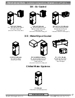
Page 17: ...with Remote Outdoor Air Cooled Condensing Unit compressor located in condensing unit VCH CCU or XCU Models DX Split Air Hanlding Unit with Remote Indoor Air Cooled Condensing Unit compressor located in condensing unit VCW VCG Models DX Self Contained Water Glycol Cooled VCC Models Chilled Water Air Handling Systems ACCESS PANEL Compressors VCH XWU XGU Models DX Split Air Handling Unit with Remote ...

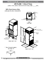
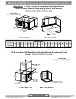
Page 18: ... Filter Access 22 88 Base 24 0 Overall 22 81 Base 24 0 Overall 76 0 91 5 with Plenum 15 5 Evaporator Return Air Inlet Grille Plenum Discharge Field Installed Optional Evaporator Supply Air Outlet REAR LEFT TOP FRONT LEFT TOP Dimensional Data Dimensional Data Up Flow MC 2x2 A C s 1 3 Tons UP FLOW 1 thru 3 Tons VCE VCH VCW VCG VCC 012 thru 036 _ ___ UF 100 Front Access Only side panels also removabl...

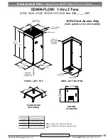
Page 19: ...r To Raised Floor 1 0 Duct Flange Connection Filter Access REAR LEFT BOTTOM FRONT LEFT TOP 22 81 C FLOOR STAND OPTIONAL 22 88 Piping Connections Utility Connections 24 0 24 0 22 81 BOTTOM PLAN VIEW 22 88 d n a t S r o o l F l e d o M C t h g i e H l a n i m o N 2 1 1 S F 0 2 1 j d A 4 1 9 8 1 1 S F 0 8 1 j d A 0 2 5 1 4 2 1 S F 0 4 2 j d A 6 2 1 2 Dimensional Data Down Flow MC 2x2 A C s 1 3 Tons D...

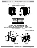
Page 20: ...Rear Left Bottom 22 88 25 0 Access Panel compressor cond coil Access Panel Condenser Blwr Mtr 40 0 4 x 3 4 Hanger Holes Front Right Top 27 0 Center Line Hanger Holes 29 0 to Outside of Hangers 38 0 Center Line Hanger Holes Hanging Rods By Others Condenser Air Inlet 12 88 6 0 14 0 23 75 3 0 14 0 3 56 1 31 19 0 Condenser Air Outlet Access Panel Cond Blwr Mtr Main Electric Box Utility Connections DX ...

Page 21: ... 012 thru 036 DIMENSIONS inches XCU XCX Model No B C E P Q R S T U V W X Y AA AB AE AF 012 018 024 030 036 44 22 34 16 16 2 3 4 6 7 8 2 16 16 2 3 8 1 5 16 1 5 24 47 1 2 50 2 Side Access 18 24 on Left Right Sides 1 3 Tons Indoor DX Water Glycol Cooled Remote Condensing Units Models CWU CGU 012 thru 036 Rear Left Bottom 22 88 25 0 Access Panel compressor Coax Vlv 20 0 4 x 3 4 Hanger Holes Front Righ...

Page 22: ..._____________________ ____________________________________________________________________ ____________________________________________________________________ ____________________________________________________________________ ____________________________________________________________________ ____________________________________________________________________ _________________________________...

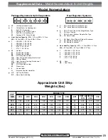
Page 23: ...ns d 1 208 230V 1 Ph 60 Hz 3 208 230V 3 Ph 60 Hz 4 460 480V 3 Ph 60 Hz 5 575V 3 Ph 60 Hz 7 277V 1 Ph 60 Hz e 00 No Heat E1 Electric Heat 1 Stage E2 Electric Heat 2 Stages ES SCR Fired Electric Heat HE Heat Pump with Auxiliary Electric Heat HG Hot Gas Reheat HP Heat Pump w o Auxiliary Electric Heat HW Hot Water Heat ES SCR Fired Electric Heat ST Steam Heat f 0 No Humidifier H Electrode Canister Hum...

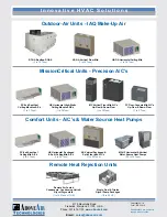
Page 24: ... Pump Packages 1 2 to 50 HP Outdoor Air Units IAQ Make Up Air HK OA Horizontal Ceiling Mtd 1 to 30 Tons VK OA Vertical Floor Mtd 1 to 30 Tons RT OA Rooftop DOAS 3 to 72 Tons MissionCritical Units Precision A C s HK Horizontal High Static Ceiling Mounted A C s 1 to 30 Tons SC 2x4 SpotCool Ceiling Mounted A C s 1 to 3 Tons Comfort Units A C s Water Source Heat Pumps FC Floor Console Mtd A C s Up Flo...

Reviews: