REV 0.0 April 18, 2023
Page 2
Environmental
The Gateway is designed for operation over the temperature range of -40°F to +140°F (-40°C to +60°C).
The Gateway enclosure is rated for NEMA 4/4X ingress protection – suitable for exposed outdoor applications.
However, the selected antenna must be suitable for the installation environment. ABM offers the following:
•
A remote magnetic-mount outdoor antenna with a 6’ (2m) SMA extension cable (standard configuration).
•
An outdoor antenna (IP66 rated) that mounts directly on the enclosure’s SMA connector.
•
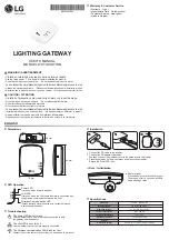
An indoor-only antenna mounted on the SMA connector (as shown in the above product photo).
If installed outdoors and unsheltered, the Gateway must be mounted vertically, such that the wiring exits from the
bottom and the antenna from the left side, to prevent a build up of water, snow or ice around the cable glands or the
SMA antenna connector. The mounting feet may be relocated to the sides of the enclosure (rather than the top and
bottom as shown in the above product photo) for further mounting flexibility.
C - Installation:
Physical Configuration
Following the proper installation of each sensor according to its supplied instructions, the Gateway should then be
installed in any location with suitable cellular reception and environmental conditions. The Gateway’s 6ft (2m) pigtail
can in many cases be wired directly to a sensor – otherwise, a junction box is required to connect it to the RS485 and
DC power buses.
It is not necessary to install the Gateway at one end of the RS485 bus (as shown in several examples in Section D) – it
can be located anywhere in the network. The RS485 cabling must be connected in a multi-drop or daisy-chain
configuration, as star configurations (i.e. with long branches) are not recommended. Short stubs are acceptable
(maximum 6ft/2m) when connecting sensors using junction boxes.
Cabling
The Gateway is supplied with two 6ft (2m) #24AWG shielded twisted-pair pigtail cables – the minimum
recommended wire size. ABM supplies all other sensor products with terminal blocks suitable for up to #14AWG
wires. These terminals also accept two #18AWG conductors, which allows for direct wiring without junction boxes in
some cases (see Section D Examples 1 and 4).
Several basic rules apply to cabling:
•
For ingress protection, it is important that only one cable per cable gland be used. Each ABM300 sensor is
supplied with two cable entries, facilitating direct connection in a multi-drop network.
•
AC versions sensors (ABM400 or ABM430) require one gland for AC power, leaving only one gland for
network connections. Line voltage (AC) conductors must not share a cable with low voltage (DC) conductors
such as RS485 or mA Output.
•
When junction boxes are used to meet the above requirements, the branch cable must not exceed 2m/6’ in
length.
•
Conduits can be used instead of cable glands to allow runs of multiple cables or wire pairs, but line voltage
cables or conductors cannot share a conduit with low voltage cables or conductors.


