10
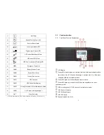
Go to next page
Go to previous page or change the setting of the UPS.
To re-confirm the change of UPS Setting
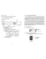
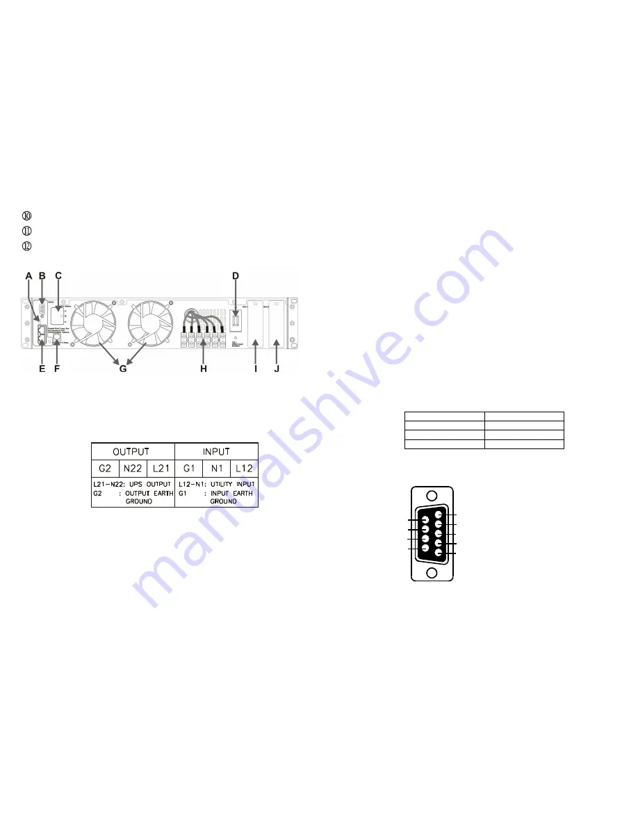
2.3.2. Rear Panel Explanation
A Terminal Resistor for Parallel function
B RS232 Port
C External Battery Connector
D Utility Input Breaker
E CAN Bus Connection Port for Parallel System
F
Maintenance Bypass Switch and Galvanic Tx. Temperature
Sensor
G Cooling Fan
H Utility Input &UPS Output Power Connector
Connection Port
I Customer Options Slot 1
J Customer Options Slot 2
11
2.4.
Communication Port Explanation
The Communication port on the UPS provides true RS232 type to
communicate with UPS software to remote monitoring the power and UPS status.
With optional interfaces cards, which contains R2E(2
nd
RS232 plus EPO),
RSE(RS485 plus EPO), USE(USB plus EPO), DCE(Dry Contact plus EPO), as
well as SNMP/ card, you may combine them according to your demand. However,
the R2E card, RSE card and USE card are prohibited to be used Simultaneously.
The bundled software of the UPS is compatible with many operating systems
such as Windows 98, & 2000, ME, NT and XP. For other applications like Novell,
NetWare, Unix, Linux, please contact your local distributor for a proper solution.
When the optional interface cards are used with onboard RS232 port in
communication, the shutdown command at the DCE card & also the EPO signals
will get the highest priority in control command, then the SNMP/WEB card , then
R2E, RSE and USE get the lowest priority.
2.4.1. True RS232 type
2.4.1.1 The RS232 interface settings
The RS232 interface shall be set as follows:
Baud Rate
2400 bps
Data Length
8 bits
Stop Bit
1 bit
Parity
None
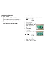
2.4.1.2 The Pin Assignments of true RS232 type
The Pin Assignments of true RS232 type are illustrated as follows:
1
2
3
4
5
6
7
8
9
Pin 3: RS232 Rx
Pin 2: RS232 Tx
Pin 5: Ground
Summary of Contents for MSII-RT
Page 26: ...50 51 192321142000000 ...


