EN
Article No.: 0301676_EN_a
Installation and Configuration Guide
METERS
METERL
Page 1: ...EN Article No 0301676_EN_a Installation and Configuration Guide METERS METERL...
Page 2: ...07 Lauf an der Pegnitz Germany 49 0 9123 188 0 49 0 9123 188 188 info abl de www ablmobility de Customer Service 49 0 9123 188 0 service abl de www ablmobility de en service support Revision 0301676_E...
Page 3: ...ducts 8 The energy meter at a glance 10 The display at a glance 11 The cable type current transformer at a glance 11 Mechanical and electrical installation 13 Selecting the connection mode 14 Installa...
Page 4: ...nal load management system for a single controller charging station or a group in stallation controlled via an eMH2 or eMH3 controller wallbox an eMC2 or eMC3 controller charging pole or via the 1V000...
Page 5: ...TE Indicates important information for operation or installation Sections marked with this symbol indicate further important information and features necessary for successful operation Actions marked...
Page 6: ...list electrical contractor who has carried out the installation of your charging station and accessories y The product housing has been damaged mechanically or the housing cover has been removed or ca...
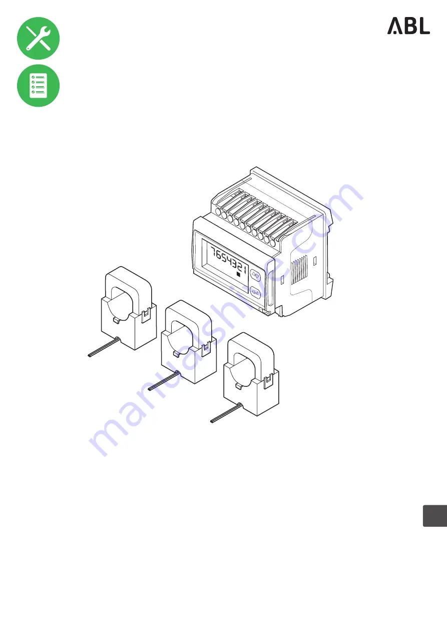
Page 7: ...210 Energy meter included in METERS and METERL front and side view all dimensions in mm Cable type current transformers up to 300 A Current transformer for attachment to a single power line included i...
Page 8: ...you have is the system suitable for your application METERL 1 St ck Externes Lastmanagement L ABL GmbH Albert B ttner Stra e 11 D 91207 Lauf www abl de Items supplied METERS METERL are supplied with t...
Page 9: ...arging sockets h 1 460 mm w 440 mm d 200 mm Housing without protrusions Charging pole eMC3 Controller 3P4412 3P4435 Calibration law compliant charging pole from ABL with two charge points either with...
Page 10: ...Setting up the energy meter on page 19 C Red LED This LED flashes red proportionally to the measured energy D Enter key This button is used to open a parameter menu to switch between the modes of the...
Page 11: ...ter software is displayed here Use the toggle key B to switch between the menus and the enter key D to activate editing in this menu K Value range The current value for the selected menu is shown here...
Page 12: ...e the black wire L is as signed to the even numbered terminals 2 4 and 6 NOTE Assignment according to connection mode Please note that depending on the selected connection mode see Selecting the conne...
Page 13: ...t measurement may have to be approved by your local grid operator Contact your local grid operator for further information Section current measurement In contrast with section current measurement the...
Page 14: ...ible connection modes The energy meter supplied with METERS METERL supports other connection types in principle although these are not required in practical use as a load management system Therefore a...
Page 15: ...t transformers You will need the following tools and components for the installation Phillips screwdriver Optional Cable tie 1 per transformer DANGER Dangerous electrical currents Always observe the 5...
Page 16: ...nt in the distributor 4 Connect the energy meter to the mains via specially fused cable taps F 315 mA y Assign the screw terminals 7 8 9 and on the energy meter in accordance with the connection mode...
Page 17: ...ted connection mode K 5A L WARNING Adhering to the electrical energy flow direction Always observe the energy flow direction and thus the installation direction for the power cable indicated by the ar...
Page 18: ...roup installation one of the two Modbus interfaces remains unassigned while the other is used for communication with the extender charging stations Wire the free interface in the controller to the RS4...
Page 19: ...her information on this in the corresponding installation manual for the charging station Setting up the energy meter To ensure accurate measurement the energy meter must be set up via its system and...
Page 20: ...ng the factory default password If required you can set a new password between 000 and 999 via the CnGPASS menu to protect the energy me ter against unauthorised access To change the password briefly...
Page 21: ...key to select the appropriate transformer ratio and hold the enter key for about 3 seconds to confirm y METERS Select the value 60 y METERL Select the value 120 1S 3S 7 Use the toggle key to select th...
Page 22: ...toggle key to select the parity EVEN and hold the enter key for about 3 seconds to confirm 1S 3S 13 Use the toggle key to select the bStoP menu for the stop bit of the energy meter and briefly press t...
Page 23: ...arry out an update in any case The instructions included in the installation package describe step by step how to perform the update The application offers a role based concept that restricts the edit...
Page 24: ...nline appli cation where you are automatically logged in with the Owner role WARNING Manually setting up the network settings If you are unable to connect to the application check your computer s netw...
Page 25: ...hen displayed next to the controller and the already selected extender charging stations in the Products Installation tab 9 Navigate to the bottom of the Products Instal lation tab and click the Creat...
Page 26: ...Installation tab and in the Actions column click the button for the Con troller charging station marked with C 16 Set the parameters for the controller y Maximum Value Enter the maximum charging curre...
Page 27: ...above Start Value Set the starting current for the charging group until the measured values from the energy meter are available here It is recommended to set the Start Value and Fallback Value the sam...
Page 28: ...tion 28 19 Then click Perform reconfiguration to restart the system 20 Switch to the Overview General tab this shows at a glance whether your system is set up correctly This completes the setup of the...
Page 29: ...digital output Dielectric strength 4 000 VAC RMS for 1 minute Noise suppression ratio CMRR 100 dB 48 to 62 Hz EMC in accordance with EN62052 11 Electrostatic discharges 15 kV air discharge Immunity to...
Page 30: ...A 10 VA IP rating IP rating Explanation IP20 Protection against penetration of solid foreign bodies with a diameter greater than 12 5 mm IP40 Protection against penetration of solid foreign bodies wit...
Page 31: ...ther spring terminal L of the next Extender charging station In both cases the individual wire strands of the Ethernet cable must be allocated as illustrated below Spring terminal Energy meter RJ45 pl...
Page 32: ...any obli gation on the part of the manufacturer The manufacturer does not take responsibility for any loss and or damage that occurs because of the data or possible misinformation contained in this ma...
Page 33: ...Copyright and disclaimer 33...
Page 34: ...MADE IN GERMANY ABL GmbH Albert Bu ttner Stra e 11 91207 Lauf an der Pegnitz Germany 49 0 9123 188 0 49 0 9123 188 188 info abl de www ablmobility de...