background image

Hardware Setup 

2-15 

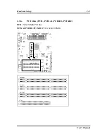
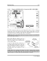
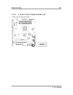
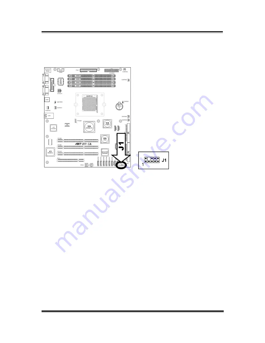
2.3.12. 

Low Pin Count Connection Header (J1) 

  (Reserved for internal testing) 


User’s Manual 

Summary of Contents for SV-1A

Page 1: ...SV 1A AMD Athlon 64 Server Board Socket 939 User s Manual Rev 1 00...

Page 2: ...ent shall the manufacturer be liable for direct indirect special incidental or consequential damages arising from any defect or error in this manual or product Product names appearing in this manual a...

Page 3: ...1 4 2 5 2 3 3 CMOS Memory Clearing Header CCMOS1 2 6 2 3 4 USB Device Wake up Connection Header USB PWR1 2 7 2 3 5 Front Panel Switches Indicators Connection Headers FPIO1 2 8 2 3 6 PCI Slots PCI1 PCI...

Page 4: ...3 2 Advanced BIOS Features 3 6 3 3 Advanced Chipset Features 3 8 3 4 Integrated Peripherals 3 11 3 5 Power Management Setup 3 16 3 6 PnP PCI Configurations 3 19 3 7 PC Health Status 3 21 3 8 Load Fai...

Page 5: ...age XL default 8MB Local memory Optional 4MB Serial ATA 4 channel Serial ATAII 3Gb s data transfer rate Marvell 88SX 6041 Default 8 channel Serial ATAII 3Gb s data transfer rate Marvell 88SX 6081 Opti...

Page 6: ...2 C Back Panel I O 1x PS 2 keyboard and mouse connector 1x COM port COM1 1x VGA port 1x Dual USB 2 0 Connector 1x Dual RJ 45 w transformer LAN Connector Miscellaneous ATX form factor 305mm x 265mm Har...

Page 7: ...Introduction 1 3 1 2 Layout User s Manual...

Page 8: ...Memory Slots FDC1 Floppy Disk Drive Connector FPIO1 Front Panel Switches Indicators Connection Headers FPUSB1 Additional USB Port Connection Header IDE1 IDE2 Hard Disk Drive Connectors J1 Low Pin Coun...

Page 9: ...therboard provides a ZIF Zero Insertion Force Socket 939 to install AMD Socket 939 CPU The CPU you bought should contain with a kit of heatsink cooling fan retention frame and back plate If that s not...

Page 10: ...MM slots for single dual channel DDR400 333 memory modules The expansible size is available up to 8GB by un buffered ECC Non ECC memory modules DIMM Population Table Single Channel Dual Channel DIMM1...

Page 11: ...to the slots until the ejector tabs at both sides of the slot automatically snaps into the mounting notch Do not force the DIMM module in with extra force as the DIMM module only fit in one direction...

Page 12: ...on the peripherals you have connected WARNING Always power off the computer and unplug the AC power cord before adding or removing any peripheral or component Failing to do so may cause severe damage...

Page 13: ...system The CPU must be kept cool by using a powerful fan with heatsink The system is capable of monitoring the speed of the CPU fan CPUFAN1 CPU Fan Power Connector SYSFAN1 System Fan Power Connector...

Page 14: ...cap to clear the CMOS memory Pin 1 2 shorted default Normal operation Pin 2 3 shorted Clear CMOS memory WARNING Turn the power off first including the 5V standby power before clearing the CMOS memory...

Page 15: ...nection Header USB PWR1 These headers use a jumper cap to enable disable the wake up function USB PWR1 Pin 1 2 shorted default Disable wake up function support at USB1 port Pin 2 3 shorted Enable wake...

Page 16: ...ase pay attention to connect these headers A wrong orientation will only cause the LED not lighting but a wrong connection of the switches could cause system malfunction HLED Pin 1 3 Connects to the H...

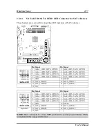
Page 17: ...Hardware Setup 2 9 2 3 6 PCI Slots PCI1 PCIXA1 PCIXB1 PCIXB2 PCI1 32bit 33MHz PCI Slot PCIXA1 PCIXB1 PCIXB2 PCI X 64bit 100MHz User s Manual...

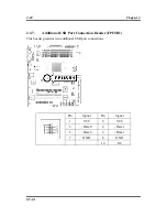
Page 18: ...pter 2 2 3 7 Additional USB Port Connection Header FPUSB1 This header provides two additional USB port connections Pin Signal Pin Signal 1 VCC 2 VCC 3 Data 0 4 Data 1 5 Data 0 6 Data 1 7 GND 8 GND 10...

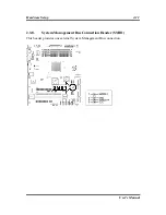
Page 19: ...Hardware Setup 2 11 2 3 8 System Management Bus Connection Header SMB1 This header provides one external System Management Bus connection User s Manual...

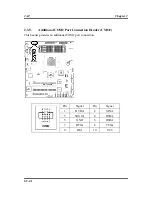
Page 20: ...ter 2 2 3 9 Additional COM2 Port Connection Header CMO2 This header provides an additional COM2 port connection Pin Signal Pin Signal 1 DCDA 2 SINA 3 SOUTA 4 DTRA 5 GND 6 DSRA 7 RTSA 8 CTSA 9 RIA 10 V...

Page 21: ...n both the FDC1 port and the floppy connector Each of the IDE port connects up to two IDE drives at Ultra ATA 100 mode by one 40 pin 80 conductor and 3 connector Ultra ATA 66 ribbon cables Connect the...

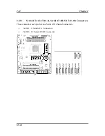
Page 22: ...4 Chapter 2 2 3 11 Serial ATA SATA1 2 Serial ATAII SATA3 10 Connectors These connectors each provide one Serial ATA channel connection SATA1 2 Serial ATA Connectors SATA3 10 Serial ATAII Connectors SV...

Page 23: ...Hardware Setup 2 15 2 3 12 Low Pin Count Connection Header J1 Reserved for internal testing User s Manual...

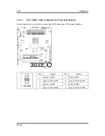
Page 24: ...r Network Interface These headers are reserved for connecting LED indicators of Network Interface Pin Signal Pin Signal 1 Active_LED1 2 Link_LED1 3 Speed_100_LED1 4 Speed_1000_LED1 5 Active_LED2 6 Lin...

Page 25: ...8 Link_LED4 SATA_GPIO3 9 GND 10 RESET 11 SATA_GPIO18 12 SATA_GPIO19 13 SATA_GPIO20 14 SATA_GPIO21 15 VCC Pin Signal Pin Signal 1 Active_LED5 SATA_GPIO12 2 Link_LED5 SATA_GPIO4 3 Active_LED6 SATA_GPIO1...

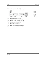
Page 26: ...15 External I O Panel Connectors Mouse PS 2 mouse connector Keyboard PS 2 keyboard connector COM1 Serial port connector VGA1 Monitor connector LAN Local Area Network connector USB1 Universal Serial B...

Page 27: ...memory count begins and then the following message appears on the screen PRESS DEL TO ENTER SETUP If this message disappears before you respond restart the system by pressing Ctrl Alt Del keys or by...

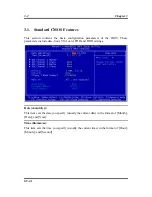
Page 28: ...BIOS These parameters include date hour VGA card FDD and HDD settings Date mm dd yy This item sets the date you specify usually the current date in the format of Month Date and Year Time hh mm ss Thi...

Page 29: ...define your own drive by yourself set it to Manual and make sure you fully understand the meaning of the parameters Please refer to the instruction manual provided by the device s manufacturer to get...

Page 30: ...ou to use 3 Mode Floppy Drive in Japanese computer system by selecting drive A B or both Leave this item to its default Disabled setting if you are not using this Japanese standard floppy drive Halt O...

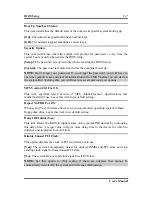
Page 31: ...e value of the base memory is typically 640K for system with 640K or more memory size installed on the motherboard Extended Memory This item displays the amount of extended memory detected during syst...

Page 32: ...is item functions only when there is the option of Hard Disk in any one of the First Second Third Boot Device items First Boot Device Second Boot Device Third Boot Device Boot Other Device Select the...

Page 33: ...r OS This item specifies which version of MPS Multi Processor Specification this motherboard will use Leave this item to its default setting Report No FDD For OS When set to Yes this item allows you t...

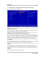
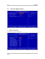
Page 34: ...3 8 Chapter 3 3 3 Advanced Chipset Features DRAM Configuration Click Enter key to enter its submenu SV 1A...

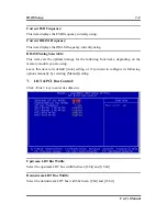
Page 35: ...ollowing four items depending on the memory module you are using Leave this item to its default Auto setting or if you want to configure its following options manually by selecting Manual setting LDT...

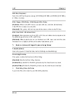
Page 36: ...r the different speed between CPU and PCI bus Disabled Data transmissions are not buffered and CPU must wait until the data transmission is complete and then start another transmission cycle Back to A...

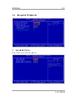
Page 37: ...BIOS Setup 3 11 3 4 Integrated Peripherals OnChip IDE Device Click Enter key to enter its submenu User s Manual...

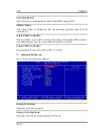
Page 38: ...This item allows you to enable or disable the primary and secondary IDE controller Select Disabled if you want to add a different hard drive controller Onboard IDE 2 Controller The description is sam...

Page 39: ...the bus mode for secondary PCI X slot Onboard LAN Controller This option enables or disables the LAN controller LAN Boot ROM This item allows you to use the boot ROM instead of a disk drive to boot u...

Page 40: ...E8 IRQ4 2E8 IRQ3 Allows you to manually select an I O address for the onboard Serial Port Disabled Disables the onboard Serial Port Onboard Parallel Port This item specifies the I O address used by th...

Page 41: ...sfer rate ECP EPP Allows parallel port operation at ECP and EPP mode EPP Mode Select This item selects the EPP mode ECP Mode Use DMA This item selects the DMA channel of the parallel port Back to Inte...

Page 42: ...he system from powering off in case you accidentally hit or pushed the power button Instant Off Pressing and then releasing the power button at once will immediately power off the system CPU THRM Thro...

Page 43: ...Resume Time hh mm ss This item sets the time you would like the system to power on POWER ON Function This item selects the way you want your system to power on Password Use a password to power on the...

Page 44: ...ion after an AC power failure Power Off When power returns after an AC power failure the system s power remains off You must press the Power button to power on the system Power On When power returns a...

Page 45: ...s Resources Controlled By This item configures all of the boot and Plug and Play compatible devices Auto ESCD The system will automatically detect the settings Manual Choose the specific IRQ resources...

Page 46: ...pt to either PCI Device or Reserved Back to PnP PCI Configurations Setup Menu PCI VGA Palette Snoop This item determines whether the MPEG ISA VESA VGA cards can work with PCI VGA or not Enabled MPEG I...

Page 47: ...BIOS Setup 3 21 3 7 PC Health Status User s Manual...

Page 48: ...cts the fan that will be monitored for malfunction Active Temp Point This item selects the point of active temperature for FANEQ option Active DC Level This item selects the 1st 2nd and 3rd DC level f...

Page 49: ...temperature that would shutdown the system automatically in order to prevent system overheats CPU Warning Temperature This item selects the CPU s warning temperature limit Once the system has detecte...

Page 50: ...ddress from 294H to 297H If you have a network adapter sound card or other add on cards that might use those I O addresses please adjust your add on card I O address to avoid using these addresses 3 8...

Page 51: ...g system and then the software drivers The necessary drivers are all included within the Drivers Utilities CD that came packaged with your workstation board The display shown in the following figure s...

Page 52: ...perating System Manual View the user s manual in PDF file Utility Click to enter the sub screen for installing software like Acrobat Reader Award Flash DirectX and LoFormat utility Browse CD Browse th...

Page 53: ...you follow the procedures outlined below before contacting us With your help we can meet our commitment to provide the best service to the greatest number of ABIT customers 1 Check the Manual It soun...

Page 54: ...em reproduction we will not be able to reply to every email Please understand that we are selling through distribution channels and don t have the resources to serve every end user However we will try...

Page 55: ...20 Sales sales abit nl Web Site http www abit nl Austria Czech Romania Bulgaria Slovakia Croatia Bosnia Serbia and Macedonia Asguard Computer Ges m b H Schmalbachstrasse 5 A 2201 Gerasdorf Wien Austri...

Page 56: ...ame Phone Number Contact Person Fax Number E mail Address Model BIOS ID Motherboard Model No DRIVER REV OS Application Hardware Name Brand Specifications CPU HDD IDE1 IDE2 CD ROM Drive IDE1 IDE2 Syste...

Reviews: