ABIMIG
®
SpinArc
®
5 Functional description
EN - 7
5 Functional description
The contact tip and welding wire move at high speed in a circular orbit. The centrifugal forces cause the filler
material to be distributed in the arc, in turn creating a weldseam. The innovative torch design enables easy
adjustment of the rotation diameter and rotational speed of the wire in order to optimise welding quality and
performance.
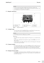
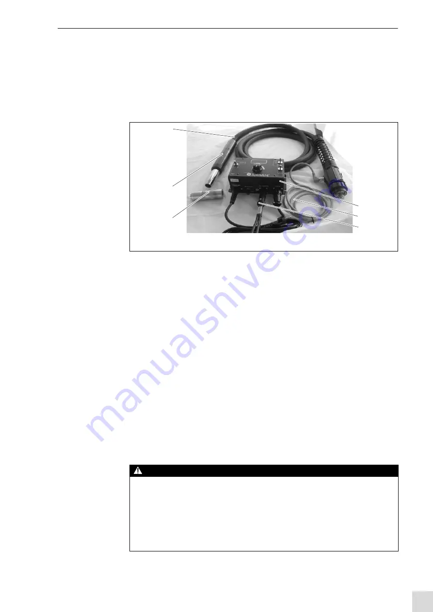
The ready-to-use welding torch system comprises:
5.1 Flexure mounting tool
This tool
is used for flexure loosening and tightening.
5.2 Cable assembly
The air-cooled cable assembly
provides the welding torch with all the supply lines required for welding,
e.g. wire, welding current and shielding gas.
5.3 Control device
The control device
is an integral component of the
ABIMIG
®
SpinArc
®
. The user interface allows you
to set the mode, rotational speed, direction of rotation and the rotation start delay.
5.4 Control lead
The control lead
connects the torch to the control device.
5.5 Trigger control cable
The trigger control cable
is needed for REMOTE operation, and is mounted between the torch guide or
robot and the wire feeder. The Amphenol connection is connected to the control device and the two
connections are connected to the trigger for the wire feeder.
6 Putting into operation
1
Cable assembly
2
Control device
3
Control lead
4
Trigger control cable
5
Flexure mounting tool
6
Torch body
Fig. 1
ABIMIG
®
SpinArc
®
welding torch system
5
6
1
2
3
4
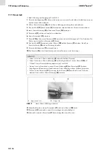
DANGER
Risk of injury due to unexpected start-up
The following instructions must be adhered to throughout all maintenance, servicing, assembly,
disassembly and repair work:
• Switch off the power source.
• Switch off the SpinArc control device.
• Switch off the entire welding system.
• Close off the gas supply.
• Disconnect all electrical connections.


