background image

14

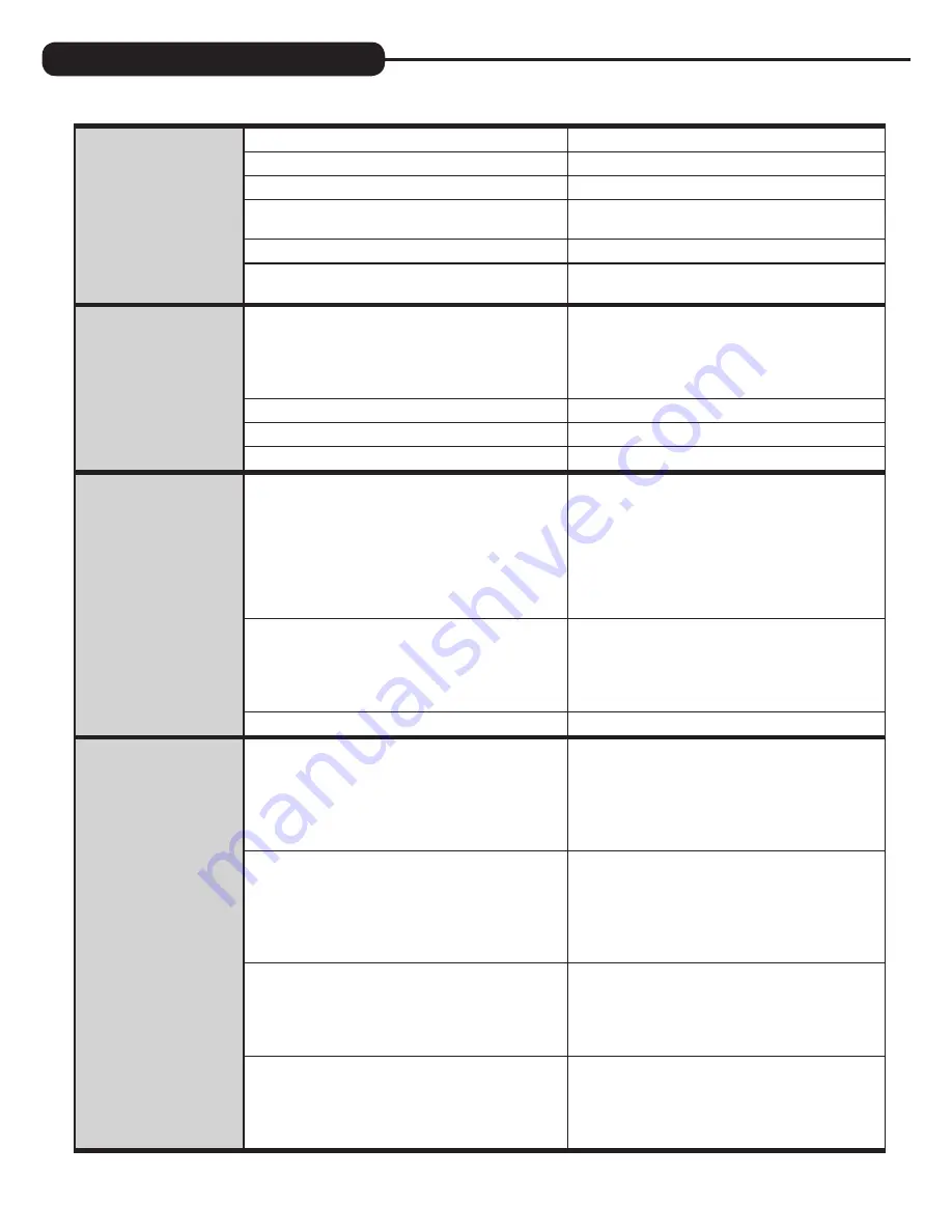
 12.   Control valve fails to 

draw in regenerant

 A . Injector is plugged

 A .  Remove injector and clean or replace

 B .  Faulty regenerant piston

 B .  Replace regenerant piston

 C . Regenerant line connection leak

 C . Inspect regenerant line for air leak

 D .  Drain line restriction or debris cause excess 

back pressure

 D .  Inspect drain line and clean to  

correct restriction

 E . Drain line too long or too high

 E .  Shorten length and or height

 F . Low water pressure

 F .  Check incoming water pressure – water  

pressure must remain at minimum of 25 psi

 13.  Water running to 

drain

 A . Power outage during regeneration

 A .  Upon power being restored control will finish 

the remaining regeneration time . Reset time of 

day . If PC board has battery back up present 

the battery may be depleted . See front cover 

and drive assembly drawing for instructions .

 B . Damaged seal/stack assembly

 B .  Replace seal/stack assembly

 C . Piston assembly failure

 C . Replace piston assembly

 D . Drive cap assembly not tightened in properly

 D .  Retighten the drive cap assembly

 14.  E1, Err – 1001,  

Err – 101 =  

Control unable  

to sense motor 

movement

 A .  Motor not inserted full to engage pinion, 

motor wires broken or disconnected

 A .  Disconnect power, make sure motor is fully 

engaged, check for broken wires, make sure  

two pin connector on motor is connected to the 

two pin connection on the PC board labeled 

MOTOR . Press NEXT and REGEN buttons for  

3 seconds to resynchronize software with piston 

position or disconnect power supply from PC 

board for 5 seconds and then reconnect .

 B . PC board not properly snapped into drive bracket

 B .  Properly snap PC board into drive bracket and 

then Press NEXT and REGEN buttons for 3 

seconds to resynchronize software with piston 

position or disconnect power supply from PC 

board for 5 seconds and then reconnect .

 C . Missing reduction gears

 C .  Replace missing gears

 15.  E2, Err – 1002, Err – 

102 = Control valve 

motor ran too short 

and was unable to 

find the next cycle 

position and stalled

 A . Foreign material is lodged in control valve

 A .  Open up control valve and pull out piston 

assembly and seal/stack assembly for 

inspection . Press NEXT and REGEN buttons for  

3 seconds to resynchronize software with piston 

position or disconnect power supply from PC 

board for 5 seconds and then reconnect .

 B . Mechanical binding

 B .  Check piston and seal/stack assembly, check 

reduction gears, check drive bracket and main 

drive gear interface . Press NEXT and REGEN 

buttons for 3 seconds to resynchronize software 

with piston position or disconnect power supply 

from PC board for 5 seconds and then reconnect .

 C . Main drive gear too tight

 C .  Loosen main drive gear . Press NEXT and 

REGEN buttons for 3 seconds to resynchronize 

software with piston position or disconnect 

power supply from PC board for 5 seconds 

and then reconnect .

 D . Improper voltage being delivered to PC board

 D .  Verify that proper voltage is being supplied . 

Press NEXT and REGEN buttons for 3 seconds 

to resynchronize software with piston position 

or disconnect power supply from PC board for 

5 seconds and then reconnect .

 PROBLEM 

CAUSE 

CORRECTION 

TROUBLESHOOTING GUIDE

Summary of Contents for iSoftenH2O

Page 1: ...1 Abendroth Water Conditioning 327 Janesville Avenue Fort Atkinson WI 53538 Phone 920 563 2507 www abendrothwater com High Efficiency On Demand Water Softeners ...

Page 2: ... cautions and notes before installing This manual should be kept for future reference If you have any questions regarding your water softener contact Abendroth Water Conditioning at 327 Janesville Avenue Fort Atkinson WI 53538 Phone 920 563 2507 Fax 920 563 3411 www abendrothwater com YOUR WATER TEST Hardness__________________________ gpg Iron_______________________________ ppm pH_________________...

Page 3: ...low Rate Capacity Remaining and Days to a Regeneration are optional displays but are not normally used Each of these can be viewed by pressing next to scroll through them When stepping through any programming if no buttons are pressed within 5 minutes the display returns to a normal user display Any changes made prior to the 5 minute time out are incorporated To quickly exit any Programming Instal...

Page 4: ...s regeneration water to the unit while also providing untreated water to the distribution system Fig 1 2 BYPASS POSITION The inlet and outlet handles point to the center of the bypass The system is isolated from the water pressure in the plumbing system Untreated water is supplied to the building Fig 2 3 DIAGNOSTIC POSITION The inlet handle points toward the control valve and the outlet handle poi...

Page 5: ... the drain and the water conditioner should be as short as possible 2 Since salt must be added periodically to the brine tank it should be in an easily accessible location 3 It is NOT recommended to install any water conditioner with less than 10 feet of piping between its outlet and the inlet of a water heater CAUTION To protect the unit in the event of a hot water heater backup the manufacturer ...

Page 6: ...o this could cause interior damage to the flow control Install a 1 2 I D flexible plastic tube to the Drain Line Assembly or discard the tubing nut and use the 3 4 NPT fitting for rigid pipe recommended If the backwash rate is greater than 7 gpm use a 3 4 drain line Where the drain line is elevated but empties into a drain below the level of the control valve form a 7 loop at the discharge end of ...

Page 7: ...owever an overflow line connection will direct the overflow to the drain instead of spilling on the floor where it could cause considerable damage This fitting is an elbow on the side of the brine tank Attach a length of 1 2 I D tubing to fitting and run to drain Do not elevate overflow line higher than 3 below bottom of overflow fitting Do not tie this tube into the drain line of the control valv...

Page 8: ...l not cycle to the next position Open the inlet handle of the bypass valve very slightly allowing water to fill the tank slowly in order to expel air CAUTION If water flows too rapidly media will be lost to the drain 3 When the water is flowing steadily to the drain without the presence of air slowly open the inlet valve Restore power and momentarily press the regen button to advance the control t...

Page 9: ...lely on gallons used If any number is set allowable range from 1 to 28 a regeneration initiation will be called for on that day even if a sufficient number of gallons were not used to call for a regeneration Set Day Override using or buttons 3 is recommended set number of days between regeneration 1 to 28 or set to OFF Press next to go to step 4 Press regen if you need to return to the previous st...

Page 10: ...hout salt To initiate a manual regeneration at the next preset regeneration time press and release regen The words REGEN TODAY will flash on the display to indicate that the system will regenerate at the next regeneration time set in Programming steps 4 and 5 If you pressed the regen button in error pressing the button again will cancel the command To initiate a manual regeneration immediately pre...

Page 11: ...gs of this water softener include a dry salt storage feature no water in brine tank between regeneration the manufacturer recommends the use of solar salt for best results The brine tank is manufactured for the use of solar pellets or rock salt If pellet or rock salt is used a cleaning of the brine tank every six months is recommended If the dry salt storage feature is not being utilized block sal...

Page 12: ... stalled meter turbine C Remove meter and check for rotation or foreign material D Meter wire not installed securely into three pin connector D Verify meter cable wires are installed securely into three pin connector labeled METER E Defective meter E Replace meter F Defective PC board F Replace PC board 4 Control valve regenerates at wrong time of day A Power outage A Reset time of day If PC board...

Page 13: ...evel in regenerant tank G Check refill setting in programming Check refill flow control for restrictions or debris and clean or replace H Damaged seal stack assembly H Replace seal stack assembly I Control valve body type and piston type mix matched I Verify proper control valve body type and piston type match J Fouled media bed J Replace media bed 9 Control valve uses too much regenerant A Improp...

Page 14: ...onnect power supply from PC board for 5 seconds and then reconnect B PC board not properly snapped into drive bracket B Properly snap PC board into drive bracket and then Press NEXT and REGEN buttons for 3 seconds to resynchronize software with piston position or disconnect power supply from PC board for 5 seconds and then reconnect C Missing reduction gears C Replace missing gears 15 E2 Err 1002 ...

Page 15: ...uttons for 3 seconds to resynchronize software with piston position or disconnect power supply from PC board for 5 seconds and then reconnect Then reprogram valve to proper setting B MAV NHBP motor wire not connected to PC board B Connect MAV NHBP motor to PC board two pin connection labeled DRIVE Press NEXT and REGEN buttons for 3 seconds to resynchronize software with piston position or disconne...

Page 16: ...iption Qty 1 FBISCV3540 Black cover 1 FBISCV3540 W Gray cover 1 2 FBISCV3107 1 Motor 1 3 FBISCV3106 1 Drive bracket spring clip 1 4 FBISCV3813WP PC board 1 5 FBISCV3110 Drive gear 12 x 36 3 6 FBISCV3109 Drive gear cover 1 Not shown FBISCV3186 Transformer 110V 12V 1 NOTE Battery Location ...

Page 17: ...nflow 1 5 FBISCV3174 Regenerant piston 1 6 FBISCV3180 O ring 337 1 7 FBISCV3105 O ring 215 1 8 FBISCV3556 Screw 1 4 20x1 1 2 18 8SS 1 9 FBISCCI 00318337 Nut 1 4 20 HEX 18 8SS 1 10 FBISCV3016 QC2 clamp assembly includes screw nut 1 11 FBISCV3452 O ring 230 1 12 FBISCV3015 WS1 QC2 Tank adapter assembly includes O rings 1 13 FBISCV3001 04 1 body assembly downflow 1 FBISCV3001 04UP 1 body assembly upf...

Page 18: ...ass cap 2 6 FBISCV3147 Bypass handle 2 7 FBISCV3148 Bypass rotor seal retainer 2 8 FBISCV3152 O ring 135 2 9 FBISCV3155 O ring 112 2 10 FBISCV3156 O ring 214 2 2 4 1 3 BRINE ELBOW ASSEMBLY Item No Part No Description Qty 1 FBISCV3195 01 Refill port plug assembly 1 2 FBISCH4615 Elbow locking clip 1 3 FBISCV4144 3 8 Elbow Parker fitting 1 4 FBISCV3163 O ring 019 1 REPLACEMENT PARTS ...

Page 19: ... I injector assembly orange FBISCV3010 1J J injector assembly light blue FBISCV3010 1K K injector assembly light green not shown FBISCV3170 O ring 011 lower not shown FBISCV3171 O ring 013 upper The injector plug and the injector each use one lower and one upper o ring WATER METER AND METER PLUG Item No Part No Description Qty 1 FBISCV3151 Nut 1 QC 1 2 FBISCV3003 Meter assembly includes items 3 4 ...

Page 20: ...elbow FBISCV3162 013 1 3 DLFC for 3 4 elbow FBISCV3162 017 1 7 DLFC for 3 4 elbow FBISCV3162 022 2 2 DLFC for 3 4 elbow FBISCV3162 027 2 7 DLFC for 3 4 elbow FBISCV3162 032 3 2 DLFC for 3 4 elbow FBISCV3162 042 4 2 DLFC for 3 4 elbow FBISCV3162 053 5 3 DLFC for 3 4 elbow 8 FBISCV3331 Drain elbow and retainer assembly Items 2 and 3 nut and insert are only used with 1 2 I D by 5 8 O D polytubing For...

Page 21: ...1 4 FBISCH1018 2 piece overflow set 1 5 FBISCH4500 48 474 air check assembly 1 2 x 48 1 6 FBISCH4620 474 float 7 1 7 FBISCH4600 50 474 safety brine valve w 5 gpm glow control 1 8 FBISCH7016 Cap 4 brine well 1 9 FBISCH4626 Nut safety brine valve stand off 1 ASSEMBLIES 10 FBISCH4700 29WR 1 5 gpm safety float assembly 18 x 33 FBISCH4700 36 5WR 1 5 gpm safety float assembly 18 x 40 SAFETY FLOAT BRINE ...

Page 22: ...ick connect 2 2 FBISCV3150 Split ring 2 3 FBISCV3105 O ring 215 2 4 FBISCV3188 Fitting 2 3 4 BRASS SWEAT Item No Part No Description Qty FBISCV3007 03 3 4 brass sweat assembly 2 1 FBISCV3151 Nut 1 quick connect 2 2 FBISCV3150 Split ring 2 3 FBISCV3105 O ring 215 2 4 FBISCV3188 01 Fitting 2 INSTALLATION FITTING ASSEMBLIES 1 PLASTIC MALE NPT Item No Part No Description Qty FBISCV3007 04 1 plastic ma...

Page 23: ...2 1 FBISCV3151 Nut 1 quick connect 2 2 FBISCV3150 Split ring 2 3 FBISCV3105 O ring 215 2 4 FBISCV3629 Fitting 2 3 4 BRASS SHARK BITE Item No Part No Description Qty FBISCV3007 12 3 4 brass Shark Bite assembly 2 1 FBISCV3151 Nut 1 quick connect 2 2 FBISCV3150 Split ring 2 3 FBISCV3105 O ring 215 2 4 FBISCV3628 Fitting 2 3 4 JOHN GUEST ELBOW Item No Part No Description Qty FBISCV3007 15 3 4 John Gue...

Page 24: ... 15 Min to Max Working Pressure PSI 30 100 30 100 30 100 30 100 30 100 Min to Max Operating Temperature ºF 33 100 33 100 33 100 33 100 33 100 Max Flow to Drain During Regeneration GPM 1 7 2 2 2 2 3 2 3 2 Amount of High Capacity Cat ion Resin Cu Ft 1 0 1 0 1 5 2 0 2 5 Electrical Requirements volts hertz 110 50 60 110 50 60 110 50 60 110 50 60 110 50 60 Pipe Size 1 1 1 1 1 Total Dimensions Media Tan...

Page 25: ...epair or replace the part or component at its expense and return part freight collect The above provisions of the warranty are valid as long as the unit is connected in compliance with local plumbing codes and in an equivalent manner and condition of the original installation and is owned by the original owner This warranty does not cover damages due to accident fire flood freezing or any other Ac...

Page 26: ...26 NOTES ...

Page 27: ...27 ...

Page 28: ... be stored in memory no matter how long the power outage Please complete the steps as shown to the right To access this mode press set clock 1 Accessed by pressing set clock 2 Adjust hours with and buttons AM PM toggles at 12 3 Press next 4 Adjust minutes with and buttons 5 Press next to complete and return to normal operation 1 Access by pressing next and button simultaneously 2 Hardness display ...

Reviews: