


Operation Manual / TPR56-F + TPR61-F
6 Removal and installation / 6.3 Installing the turbocharger
© Copyright 2018 . All rights reserved.
HZTL2499_EN
Revision F
December 2018
6.3 Installing the turbocharger
Oil orifice plate
There is an orifice in each of the two oil inlet channels of the bearing cas-
ing. The diameter of this orifice has been individually adapted by the en-
ginebuilder for the purpose of adjusting the oil pressure. When the tur-
bocharger is exchanged, always make sure that the orifice with the cor-
rect diameter is installed in the oil-feeding oil inlet channel.
u
Reuse the same orifice that was installed before.
6.3.1
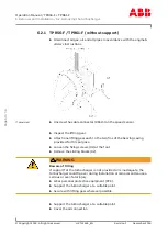
TPR56-F28/TPR61-F66 (with support)
u
Remove the cover from the oil connection.
Product
Tightening torque
of nuts (03)
TPR56-F28
415 Nm
TPR61-F66
Enginebuilder’s specifications
u
Inspect the lifting gear.
u
Attach one lifting gear each to the two fins of the bearing casing
provided for this purpose.
u
Align turbocharger on bracket.
Nuts must be compliant with ISO strength class 8.8.
Only TPR56-F28
u
Tighten nuts (03) in accordance with the specifications in the table.
Only TPR61-F66
u
Secure turbocharger with support in accordance with the engineb-
uilder’s instructions.
If provided
u
Plug in the cable connector (86515) onto the speed sensor.
Page
52
/
56


