


VSN700 Data Logger Product Manual
- 18 -
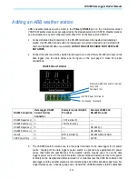
Adding an ABB weather station
ABB’s weather stations must be wired to the Primary RS-485 port on the Commercial version
VSN700. Weather stations are not supported by the Residential version VSN700. Weather stations
can be attached to any port configured for Modbus RTU on the Max version VSN700.
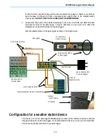
1.
Connect shielded twisted-pair wire to the RS-485 terminals on the weather/environmental
station. Use RS-485 data wire with one twisted pair, one ground conductor, and a shield with
drain wire (Belden#3106A or equivalent). DO NOT USE CAT5/6 CABLE FOR THE RS-485
DATA WIRE.
2.
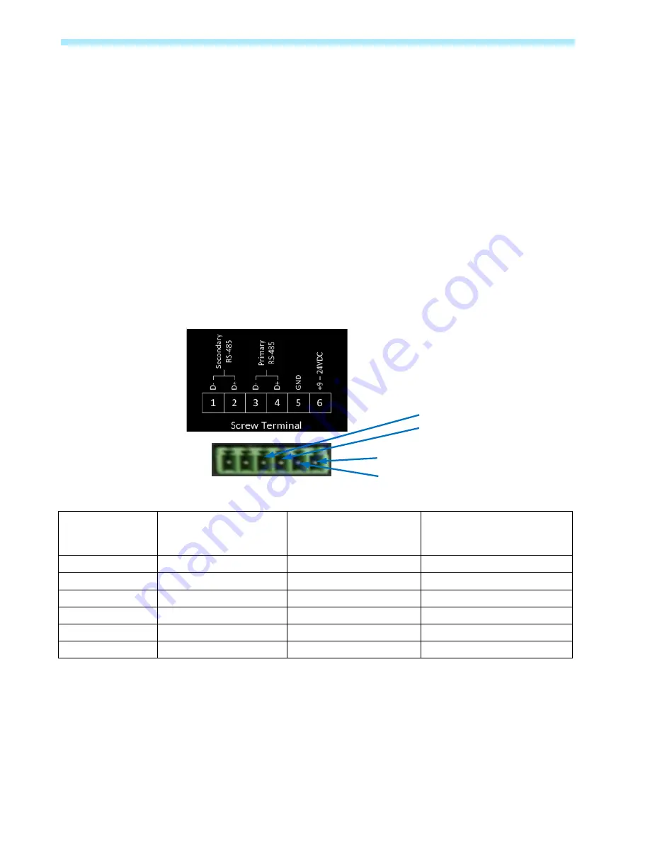
Connect the other end of the shielded twisted-pair wire to the Primary RS-485 terminals on the
data logger. Use the table below and the figure on the next page to make the proper
connections.
RS-485 Screw Terminal
RS-485 Connection
Data Logger RS-485
Screw Terminal
Connector
Example Inverter RS-485
Pin Label
Example VSN800-XX
RS-485 Pin Label
RS-485 Negative (-) 1
-TR (Terminal 5)
----
RS-485 Positive (+) 2
+TR (Terminal 4)
----
RS-485 Negative (-) 3
-----
RS-485 A(-)
RS-485 Positive (+) 4
----
RS-485 B(+)
Ground
5
RTN (Terminal 3)
RS-485 GND and GND
VDC Power Only
6
N/A
24VDC
3.
The VSN800 weather stations can tap the power terminals on the data logger for its power
source. Tapping off the data logger’s power source is optional; any appropriate DC power
source that meets the specifications of the weather station may be used. To use the data
logger’s power source for the weather station, connect shielded twisted-pair wire to the power
terminals on the weather/environmental station. For distances less than 400 feet between the
data logger and the weather station we recommend using #22 AWG stranded copper wire. For
longer distances use a heavier gauge wire. Consult the VSN800 weather station’s datasheet
+12VDC Power, Terminal 6
DC Ground, Terminal 5
Primary RS-485 Connectors, Terminal
3 (D-) and
Terminal 4 (D+)


