5
0,05 0,1
2
3 4 5 6 78
9
10
20 3040
50
0,2 0,3
0,4
0,5
0,6
0,7
1
2
2
2
2
1,5
3
3
3
3
4
4
4
4
5
5
5
5
6
6
6
6
7
7
7
7
8
8
8
8
9
9
9
9
6
7
89
10
Ia
(kA)
In = 1250 A
In = 630 A
V 1
M
- 12 kV, 630 A, 25 kA
- 12-17,5 kV, 1250 A, 25 kA
- 17,5 kV, 630 A, 20 kA
<
5
4
3
2
10
10
10
10
N.
N.
5
0,05 0,1
2
3 4 5 6 78
9
10
20 3040
50
0,2 0,3
0,4
0,5
0,6
0,7
1
2
2
2
2
1,5
3
3
3
3
4
4
4
4
5
5
5
5
6
6
6
6
7
7
7
7
8
8
8
8
9
9
9
9
5
4
3
2
10
10
10
10
6
7
89
10
Ia
(kA)
12 kV
17,5-24 kV
5
0,05 0,1
2
3 4 5 6 78
9
10
20 3040
50
0,2 0,3
0,4
0,5
0,6
0,7
1
2
2
2
2
1,5
3
3
3
3
4
4
4
4
5
5
5
5
6
6
6
6
7
7
7
7
8
8
8
8
9
9
9
9
6
7
89
10
Ia
(kA)
V 1
M
- 12-17,5 kV, 630/1250 A, 31,5 kA
In = 1250 A
In = 630 A
5
4
3
2
10
10
10
10
N.
38
VM1
- USER MANUAL
—
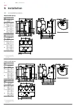
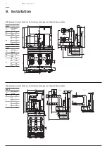
9. Installation
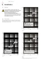
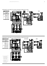
9.2. Trip curves
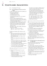
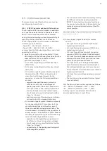
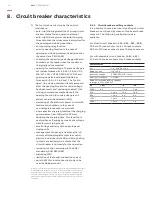
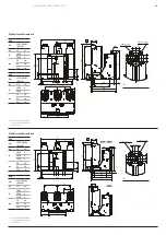
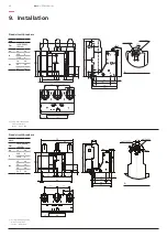
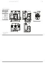
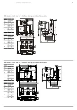
The following graphs show the number of closing-opening
cycles (No.) allowed, of the vacuum interrupters, according
to the breaking capacity (Ia).
Fig. 12a
Fig. 12b
Caption
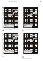
Nr. Number of closing-opening cycles allowed for the vacuum interrupters.
Ia Breaking capacity of the vacuum interrupters.
Fig. 12c
9.1. General
Correct installation is of prime importance. The
manufacturer’s instructions must be carefully studied
and followed. It is good practice to use gloves to
handle the pieces during installation.
The areas involved by the passage of power
conductors or conductors of auxiliary circuits must be
protected against access of any animals which might
cause damage or disservices.
Summary of Contents for VM1
Page 59: ...MEDIUM VOLTAGE PRODUCTS 59 59 ...

