ABB vital 1 Manual Download Page 9

ABB

5:14

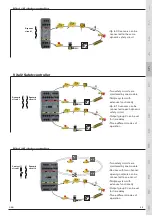
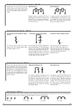
Time delay - Vital 2

Output group 2 can have disconnection delay by connecting inputs 0.5s and 1.0s being connected to +24 V. The system is binary, which 
means that the time values of the inputs are added together to give the total delay time.

V

V

9

No delay

V

V

9

0.5 s delay

V

V

9

1.0 s delay

V

V

9

1.5 s delay

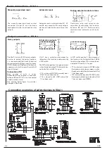
Connection of reset - Vital 2

Automatic reset

Manual monitored reset

For manual resetting, a push button must 
be  connected  between  X1  (Reset  1)  or 
X11 (Reset 2) and +24 V. The monitoring 
contactors  for  external  devices  are  to  be 
connected in series with the push button. 
For manual reset, X4 (for Reset 1) and X14 
(for Reset 2) serve as output for resetting 
the indicator lamps. 

For automatic reset, X1 and X4 (Auto reset 
1) or X11 and X14 (Auto reset 2) must be 
connected to +24 V. Monitoring contacts 
for  external  devices  must  be  connected 
b24 V and X1 (Auto reset 1) or 
X11 (Auto reset 2) . If monitoring contacts 
are  not  used,  X1  and  X11  must  be  con-
nected to +24 V.

;

;

9

9

;

;

;

;

9

;

;

There are two separate reset functions; Re-
set 1 and Reset 2. The function of these is 
dependent on the operating mode selected 
(see Selection of operating mode). Reset 1 

and Reset 2 can be configured for manual 
or automatic reset independently of each 
other by means of the input's Auto reset 1 
and Auto reset 2.

Connection of outputs - Vital 2

4

4

/

/

9

4

4

9

4

The safe relay outputs that are duplicated in 
series break between 1L-Q1 (output group 
1) and 11L-Q11 (output group 2). The loads 

that break should be fitted with spark ar-
resters to protect the outputs. The correct 
selection of VDR circuit, RC circuit or diode 
is appropriate. Note that the diode extends 
the disconnection time of the load.

The  safe  transistor  outputs  Q2  (output 
group 1) and Q12 (output group 2) have 
an output voltage of -24 V.

Connection of safe transistor output 
(-24 V)

Connection of information output

Connection of safe relay output

The non-safe transistor output Q13 is 
high (+24 V) when the outputs from 
output group 2 are active. The function 
is therefore dependent on the operating 
mode selected (see Selection of 
operating mode).

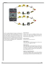
Connection of protection/sensors - Vital 2

Depending  on  the  input  function  and  the 
number of sensors connected to the safety 

circuit

 (odd or even number), the dynamic 

signal is connected between different ter-
minals;

Input function 2:

5

7

5

7

5

5

A dynamic signal is transmitted from T1, and 
depending on the number of sensors in the 
safety 

circuit

, the signal connects back to 

R1 (odd number of sensors) or R2 (even 
number of sensors).

A dynamic signal is transmitted from T11, 
and depending on the number of sensors 
in the safety 

circuit

, the signal connects 

back  to  R11  (odd  number  of  sensors)  or 
R12 (even number of sensors).

Input function 1:

Summary of Contents for vital 1

Page 1: ...ors can be connected in series and monitored with a single safety controller A dynamic signal is sent from Vital through all connected sensors and then returned to Vital which then evaluates the recei...

Page 2: ...monitored by one module Simple system with extensive functionality Up to 10 sensors can be connected to each dynamic safety circuit Output group 2 can be set for time delay Three different modes of o...

Page 3: ...manually supervised and automatic reset can be used Vital 1 has a switching relay output for information The function is determined by a DIP switch TheDIPswitchposition1 originalposition is the inform...

Page 4: ...00 m Maximum number of units varies depending on the installation and cable size For more information see the examples in this chapter Response time At Power on When activating input output When deact...

Page 5: ...ABB 5 10 Connection of units and cable lengths to Vital 1...

Page 6: ...6 Tina 4A units can be connected to one Vital 1 equivalent to 30 Eden Tina units with a total cable length of 600 metres 0 75 mm2 to Tina 4A Example Either 2 x 500 metre cables 0 75 mm2 from the contr...

Page 7: ...ch as Eden Tina and Spot can easily be con nected in series Up to 10 Eden or Tina devices can be con nected in series per input function Input function 2 The same function as input function 1 Output g...

Page 8: ...trols output group 2 Operating mode M2 Input 1 master function Vital 2 Input function 1 stops all outputs and input function 2 stops output group 2 Operating mode M3 Parallel function Vital 2 Input fu...

Page 9: ...put s Auto reset 1 and Auto reset 2 Connection of outputs Vital 2 4 4 9 4 4 9 4 The safe relay outputs that are duplicated in series break between 1L Q1 output group 1 and 11L Q11 output group 2 The l...

Page 10: ...ion Spot 10 1 Spot 35 3 Total max cable length depending on the number of Spot T R 100 m Maximum number of units varies depending on the installation andcable size For more information see the example...

Page 11: ...with the dynamic signal and the other with static 24 VDC Input function 2 A dynamic safety circuit where ABB Jokab Safety s safety sensors Eden Tina and Spot can easily be connected in se ries Up to 1...

Page 12: ...s output group 2 Operating mode M3 Parallel function Vital 3 Input function 1 and input function 2 operate in parallel and control all out puts Reset Auto reset 1 resets both input functions Reset Aut...

Page 13: ...by means of the input s Auto reset 1 and Auto reset 2 Connection of outputs Vital 3 4 4 9 4 4 9 4 The safe relay outputs that are duplicated in series break between 1L Q1 output group 1 and 11L Q11 ou...

Page 14: ...pot 35 3 Total max cable length depending on the number of Spot T R 100 m Maximum number of units varies depending on the installation andcable size For more information see the examples in this chapt...

Reviews: