


19
—
Maintenance must only be carried out by ABB personnel or in any case
by suitably qualified personnel who have in-depth knowledge of the
apparatus (IEC62271-1). Should the maintenance be carried out by
non-ABB personnel, they are responsible for the interventions.
Replacement of any parts not included in the “list of spare parts / accessories” must only be carried out
by ABB personnel.
In particular:
• Complete pole with bushings / connections
• Operating mechanism
• Closing spring unit
• Opening spring
• Spring charging geared motor with electrical signaling spring charged
• Epoxy bushing assembly
• Fixed contact
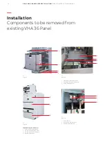
—
Maintenance
—
Electrical diagram
The standard VD4 circuit-breaker electric circuit diagram is as follows:
• VD4 electric diagram
Each circuit-breaker is always provided with the standard electric diagram or with a specific
diagram in the case of a circuit-breaker with non-standard cabling.
The standard VD4 circuit breaker electric diagram is as per drawing 1VYN300901-UJ
Wiring of auxiliary circuits
• The auxiliary circuits of the withdrawable circuit- breaker are fully cabled in the factory up to male
connector.
• For the external connections, please refer to the electric diagram of the enclosure or of the
switchgear. The Female connector in the old panel must be replaced with the corresponding female
connector suitable for male connector of CB & cabling of the panel to be done up to the female
connector during installation
Summary of Contents for VD4 Series
Page 23: ......