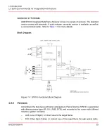
Field site shall p24V
DC
to SF910i through external power supply modules. Target
acceptable input power supply voltage range: +24V
DC
, <= +20%, >= -25%, as claimed
in
. It shall have CE mark and fulfil the requirement of SELV/PELV according
to EN 50178 1997 Electronic Equipment in Power Installations.
For SIL2 application, the customer suggest to provide the redundancy power supply,
shall with power voter that will have extra 24V over-voltage protection with threshold
no more than 35VDC, to ensure the maximum power input to SF910i shall not
exceed 35VDC even when power supply enter critical failure mode.
For SIL2 safety, IEC 60730-1, CAN/CSA E60730-1, or EN298 application, Safe-relay
need to be set into “second flame relay” condition, and needs to be serially connected
with Flame-relay contacts by customer to fulfil safety redundancy output.
Despite having inrush current limitation circuits, the inrush current measured when
there is a step application of 24V
DC
peaks to a relatively high value and settles in a
few ms (see
). Consider this when selecting the appropriate power
distribution circuit breakers or fuses to be used with SF910i. See
for
the inrush current value.
The internal non-replaceable fuse is intended to protect against internal damage in case
of excess current consumption.
SF910i is protected against polarity inversion of the 24V
DC
power supply.
Individual protection against overload or short circuit realized on external power distribution
panel shall be suitably rated, with time lag. ABB suggests mounting a dedicated circuit
breaker for each scanner, for instance, a thermal-magnetic circuit breaker, 1A curve “K”.
2.2.3
Relays
There are two relays in the SF910i. One is the main flame relay and the other is
configurable with internal parameter, for example:
–
Second flame relay
–
Watch dog
–
Flame quality
–
Scanner case skin temperature
The relay contacts are galvanic isolated.
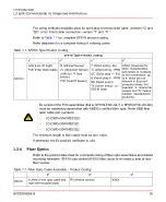
reports the relay assignment
summary.
8VZZ005286 B
35
2 Hardware
2.2 Display and Terminations Boards
Summary of Contents for Uvisor SF910i
Page 2: ......
Page 6: ......
Page 20: ...8VZZ005286 B 20...
Page 30: ...8VZZ005286 B 30...
Page 68: ...8VZZ005286 B 68...
Page 78: ...8VZZ005286 B 78...
Page 90: ...8VZZ005286 B 90...
Page 92: ...8VZZ005286 B 92...
Page 98: ...8VZZ005286 B 98...
Page 108: ...8VZZ005286 B 108...
Page 114: ...8VZZ005286 B 114...
Page 118: ...8VZZ005286 B 118...
Page 126: ...8VZZ005286 B 126...
Page 128: ...8VZZ005286 B 128...
Page 130: ...8VZZ005286 B 130...
Page 150: ...8VZZ005286 B 150...
Page 151: ...Appendix E Drawings 8VZZ005286 B 151 E Drawings...
Page 152: ...Figure E 1 Enclosure Quick Release Connector and Version LOS 8VZZ005286 B 152 E Drawings...
Page 153: ...Figure E 2 Enclosure NPT Cable Inlet and Version LOS 8VZZ005286 B 153 E Drawings...
Page 154: ...Figure E 3 Enclosure Quick Release Connector and Version FOC 8VZZ005286 B 154 E Drawings...
Page 155: ...Figure E 4 Enclosure NPT Cable Inlet and Version FOC 8VZZ005286 B 155 E Drawings...
Page 156: ...Figure E 5 FOC Flexible Assembly 8VZZ005286 B 156 E Drawings...
Page 157: ...Figure E 6 FOC Rigid Assembly 8VZZ005286 B 157 E Drawings...
Page 160: ...Figure E 9 Bailey Flame ON Standard Replacement 8VZZ005286 B 160 E Drawings...
Page 161: ...Figure E 10 Typical Bailey Flame ON Installation 8VZZ005286 B 161 E Drawings...
Page 162: ...8VZZ005286 B 162...
Page 170: ...8VZZ005286 B 170...
Page 178: ...G 7 Counter Flange 8VZZ005286 B 178 G Fittings G 7 Counter Flange...
Page 189: ......

